
Page 203 - Chemical Process Equipment - Selection and Design
P. 203
8.2. MEAN TEMPERATURE DIFFERENCE 175
f
Level
e
control
1
Liquid
t
Bottoms
Section -support
I
Air
Hot
fluid in support
Hot
fluid out
(i)
0 01 02 03 04 05 Ofi 07 08 09 10
P
(a)
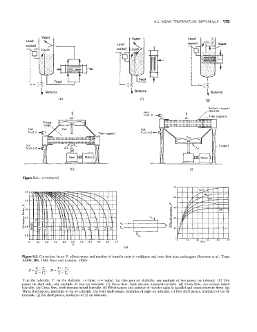
Figure 8.5. Correction factor F, effectiveness and number of transfer units in multipass and cross flow heat exchangers (Bowman et al., Trans
ASME 283, 1940; Kays and London, 1984):
T on the tubeside, T' on the shellside. i =input, o = output. (a) One pass on shellside, any multiple of two passes on tubeside. (b) Two
passes on shell side, any multiple of four on tubeside. (c) Cross flow, both streams unmixed laterally. (d) Cross flow, one stream mixed
laterally. (e) Cross flow, both streams mixed laterally. (f) Effectiveness and number of transfer units in parallel and countercurrent flows. (g)
Three shell passes, multiples of six on tubeside. (h) Four shell passes, multiples of eight on tubeside. (i) Five shell passes, multiples of ten on
tubeside. (j) Six shell passes, multiples of 12 on tubeside.