
Page 324 - Chemical Process Equipment - Selection and Design
P. 324
288 MIXING AND AGITATION
Side entering propellors are placed 18-24 in. above a flat tank
floor with the shaft horizontal and at a 10” horizontal angle with the
Baffle width, centerline of the tank; such mixers are used only for viscosities
w = D,/ 12 below 500 CP or so.
Offset = w I 6 Draft tube In dispersing gases, the gas should be fed directly below the
L impeller or at the periphery of the impeller. Such arrangements also
i 10.2. KINDS OF IMPELLERS
are desirable for mixing liquids.
J
A rotating impeller in a fluid imparts flow and shear to it, the shear
resulting from the flow of one portion of the fluid past another.
Limiting cases of flow are in the axial or radial directions so that
H12
impellers are classified conveniently according to which of these
flows is dominant. By reason of reflections from vessel surfaces and
obstruction by baffles and other internals, however, flow patterns in
most cases are mixed. When a close approach to axial flow is
particularly desirable, as for suspension of the solids of a slurry, the
Offset impeller may be housed in a draft tube; and when radial flow is
f needed, a shrouded turbine consisting of a rotor and a stator may
H16 be employed.
Because the performance of a particular shape of impeller
usually cannot be predicted quantitatively, impeller design is largely
an exercise of judgment so a considerable variety has been put forth
by various manufacturers. A few common types are illustrated on
Figure 10.2 and are described as follows:
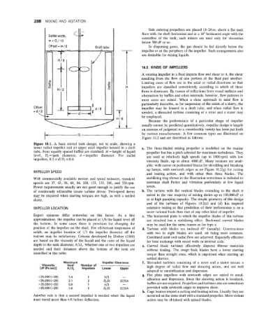
Figure 10.1. A basic stirred tank design, not to scale, showing a
lower radial impeller and an upper axial impeller housed in a draft a. The three-bladed mixing propeller is modelled on the marine
tube. Four equally spaced baffles are standard. H = height of liquid propeller but has a pitch selected for maximum turbulence. They
level, D, = tank diameter, d = impeller diameter. For radial are used at relatively high speeds (up to 1800rpm) with low
impellers, 0.3 5 d/D, 5 0.6.
viscosity fluids, up to about 4000cP. Many versions are avail-
able: with cutout or perforated blades for shredding and breaking
up lumps, with sawtooth edges as on Figure 10.2(g) for cutting
IMPELLER SPEED
and tearing action, and with other than three blades. The
With commercially available motors and speed reducers, standard stabilizing ring shown in the illustration sometimes is included to
speeds are 37, 45, 56, 68, 84, 100, 125, 155, 190, and 320rpm. minimize shaft flutter and vibration particularly at low liquid
Power requirements usually are not great enough to justify the use levels.
of continously adjustable steam turbine drives. Two-speed drives b. The turbine with flat vertical blades extending to the shaft is
may be required when starting torques are high, as with a settled suited to the vast majority of mixing duties up to 100,000 CP or
slurry. so at high pumping capacity. The simple geometry of this design
and of the turbines of Figures 10.2(c) and (d) has inspired
IMPELLER LOCATION extensive testing so that prediction of their performance is on a
more rational basis than that of any other kind of impeller.
Expert opinions differ somewhat on this factor. As a first c. The horizontal plate to which the impeller blades of this turbine
approximation, the impeller can be placed at 1/6 the liquid level off are attached has a stabilizing effect. Backward curved blades
the bottom. In some cases there is provision for changing the may be used for the same reason as for type e.
position of the impeller on the shaft. For off-bottom suspension of d. Turbine with blades are inclined 45” (usually). Constructions
solids, an impeller location of 1/3 the impeller diameter off the with two to eight blades are used, six being most common.
bottom may be satisfactory. Criteria developed by Dickey (1984) Combined axial and radial flow are achieved. Especially effective
are based on the viscosity of the liquid and the ratio of the liquid for heat exchange with vessel walls or internal coils.
depth to the tank diameter, h/D,. Whether one or two impellers are e. Curved blade turbines effectively disperse fibrous materials
needed and their distances above the bottom of the tank are without fouling. The swept back blades have a lower starting
identified in this table: torque than straight ones, which is important when starting up
settled slurries.
Maximum Impeller Clearance f. Shrouded turbines consisting of a rotor and a stator ensure a
Viscosity level Number of high degree of radial flow and shearing action, and are well
[cP (Pa sec)] h/Df Impellers Lower Upper
adapted to emulsification and dispersion.
- g. Flat plate impellers with sawtooth edges are suited to emul-
<25,000 (<25) 1.4 1 hi3 sification and dispersion. Since the shearing action is localized,
<25,000 (<25) 2.1 2 Q/3 W3)h baffles are not required. Propellers and turbines also are sometimes
>25,000 (>25) 0.8 1 h/3 -
>25,000 (>25) 1.6 2 Dt /3 (2/3)h provided with sawtooth edges to improve shear.
h. Cage beaters impart a cutting and beating action. Usually they are
Another rule is that a second impeller is needed when the liquid mounted on the same shaft with a standard propeller. More violent
must travel more than 4 ft before deflection. action may be obtained with spined blades.