Page 320 - Chemical Process Equipment - Selection and Design
P. 320

284  DRYERS AND  COOLING  TOWERS


                                                    95
                                                  LL
                LL                                e
                                                  W
                                                    90
                                                  4
                                                  a
                                                  W
                                                  a
                                                  3 85
                                                  c-
                                                  a
                                                  W
                                                  b-
                                                  5  00
                                                  0
                                                  J
                                                  0
                                                  0
                                                    75
                   60    65    70    75    BO         60   65    70    75    00        60    65    70    75     80
                       AIR  WET-BULB  TEMPERATURE  (OF)   AIR  WET - BULB  TEMPERATURE  (OF)   AIR  WET-BULB  TEMPERATURE  ('F  1
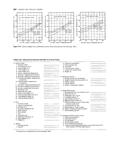
               Figure 9.19. Typical cooling tower performance curves (Cheremisinoff and  Cheremisinoff, 198f).


                TABLE 9.20. Selected Data Required with Bids of Cooling Towers
                A.  Cooling Tower                                    3.  Type and manufacturer
                   1.  Number of cells                               4.  Full load speed, rpm
                   2.  Cell dimensions, ft, in.                      5.  Frame size
                   3. Tower lenath. ft. in.                          6.  Full load current, amps
                           -..
                   4.  Tower width, ft, in.                          7.  Locked rotor current amps
                   5.  Tower height, ft, in.                         8.  Weight, Ib
                   6.  Casing, material and dimensions
                   7.  Structure, material and dimensions
                   8.  Fill decks, material and dimensions         H.  Distribution System
                   9.  Partitions and baffles, materials and          1.  Number and size of inlet flanges
                      dimensions                                     2.  Height of water inlet above curb, ft, in.
                  10.  Drift eliminators,  material and              3.  Header material
                      dimensions                                     4.  Lateral material
                  11.  Fan stacks, material and dimensions           5.  Nozzle, or downspout material
                  12.  Fan deck,  material and dimensions
                  13.  Louvers, material and dimensions
                  14. Board feet of fill                           J.  Design Performance
                  15.  Board feet total tower                         1.  Pumping head from top of basin curb, ft
                  16. Height of fan stacks, ft, in.                   2.  Spray loss, max %
                  17.  Post extension below curb, ft, in.            3.  Evaporation loss, max %
                  18.  Total shipping weight,  Ib                    4.  Fill wetted surface, ft'
                  19.  Total operating weight,  Ib                    5.  Total wetted surface, ft'
                                                                     6.  Effective splash surface, ft'
                8.  Fans                                              7.  Effective cooling volume, ft3 (from elimi-
                   1.  Number of units                                   nators to water level)
                   2.  Type and manufacturer                         8.  Air volume per fan, cfm
                   3.  Diameter, ft, in.                             9.  Static pressure, inches of water
                   4.  Number of blades per fan                      10.  Output horsepower/motor/(turbine)
                   5.  Blade material                                11.  Tower loading, gpm/ft2
                   6.  Hub material
                   7.  rpm
                   8.  Tip speed, fpm                              K.  Drawings and Performance Curves
                   9.  Mechanical efficiency, %                       1. Tower outline elevation
                  10.  Static efficiency, %                           2.  Foundation outline
                  11.  Weight, Ib                                     3.  Fill rack details
                                                                      4.  Drift eliminator details
                C.  Motors                                            5.  Tower sheeting arrangement
                   1.  Number of units                                6.  A series of guaranteed performance curves within limits of CTI
                   2.  Size, HP                                          Test Procedure ATP-105,  latest revision

                   (Excerpted from Cheremisinoff and Cheremisinoff, 1981).
   315   316   317   318   319   320   321   322   323   324   325