
Page 315 - Chemical Process Equipment - Selection and Design
P. 315
9.11. THEORV OF AIR-WATER INTERACTION IN PACKED TOWERS
EXAMPLE 9.10 Enthalpy loss of air is
a Spray Dryer on the Basis of Biot Plant Data
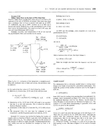
Feed to a spray dryer contains 20% solids and is to be dried to 5% 0.1(69.8 - 28.0) = 4.2 Btu/lb.
moisture at the rate of 500 lb/hr of product. Pilot plant data show
that a residence: time of 6sec is needed with inlet air of 230°F, Exit enthalpy of air is
W = 0.008 lb/lb, and exit at 100°F. Ambient air is at 70°F and is
heated with steam. Enthalpy loss to the surroundings is 10% of the h = 69.8 - 4.2 = 65.6.
heat load on the steam heater. The vessel is to have a 60" cone. Air
rate and vessel dimensions will be found. At 100°F and this enthalpy, other properties are read off the
Enthalpy, humidity, and temperatures of the air are read off
the psychrometric chart and recorded on the sketch. psychrometric chart as
H = 0.0375 lb/lb,
Dry 475pph V= 14.9cufthb.
- Water 1900 pph Air rate is
70 F A= 1900 - 25 = 63,559 lb/hr
0.0375 - 0.008
H = 0.008 h = = 69.8 o'oo8 1 q,osL=
I? = 28.0 0.1 Q
3600 2
With a residence time of 6 sec, the dryer volume is
V, = 287(6) = 1721.4 cuft.
Make the straight side four times the diameter and the cone
60":
Dry 475pph 0.866~0~
1721.4 = 4D(nD2/4) + ~- - 3.3683D3,
Water 23pph 12
Total 500 pph :. D = 8.0 ft.
When kJk, -+ cot evaluation of the integrands is straightforward. TOWER HEIGHT
When the coefficient ratio is finite and known, this procedure may
be followed: The information that is ultimately needed about a cooling tower
design is the height of packing for a prescribed performance. This
equals the product of the number of transfer units by the height of
1. For each of the four values of T, find h from Eq. (9.30). each one,
2. Eliminate h, between Eqs. (9.31) and (9.32) with the result
Z = (NTU)(HTU). (9.37)
Some HTU data for cooling tower packing have been published, for
example, those summarized on Figure 9.16. Other data appear in
the additional literature cited for this chapter. Several kinds of
3. Substitution of Eq. (9.339 into (9.36) will result in an equation tower fill made of redwood slats are illustrated in Figure 9.17. The
that has T, 2s the only unknown. This is solved for with the numbers N of such decks corresponding to particular NTUs and
Newton-Raphson method. (L/G)s are given by the equation
4. Substitution of this value of T, back into Eq. (9.31) will evaluate [(NTU) - 0.07](L/G)b
h,. N= (9.38)
5. The integrand l/(h3 -h) now may be evaluated at each a
temperature and the integration performed with Eq. (9.35). Values of a and b are given for each type of fill with Figure 9.17.
These data are stated to be for 120°F inlet water. Although the
Example 9.11 employs this method for finding the number of authors state that corrections should be estimated for other
transfer units as a function of liquid to gas ratio, both with finite and temperatures, they do not indicate how this is to be done. For
infinite values of' k,/k,. The computer programs for the solution of example, with deck type C, NTU=2 and &/G = 1.2: N=
this example are short but highly desirable. Graphical methods have (2 - 0.07)(1.2)0.60/0.092 = 23.4 decks, or a total of 31.2 ft since the
been widely used and are described for iexample by Foust et al. deck spacing is 16 in. The data of Figure 9.16 are used in Example
(1980). 9.11.