
Page 329 - Chemical Process Equipment - Selection and Design
P. 329
10.4. POWER CONSUMPTION AND PUMPING RATE 293
Type No. baffles NP N,
Propeller 0 0.3
Propeller 3-8 0.33-0.37 0.40-0.55
Turbine, vertical blade 0 0.93-1.08 0.33-0.34
Turbine, vertical blade 4 3-5 0.70-0.85
Pitched turbine, 45" 0 0.7 0.3
Pitched turbine, 45" 4 1.30-1.40 0.60-0.87
Anchor 0 0.28
A correlation of pumping rate of pitched turbines is shown a3
Figure 10.7.
Power input per unit volume as a measure of mixing intensity
or quality was cited in Section 10.3 and in Chapter 17. From the
correlations cited in this section, it is clear that power input and
Reynolds number together determine also the pumping rate of a
given design of impeller. This fact has been made the basis of a
method of agitator system design by the staff of Chemineer. The
superficial linear velocity-the volumetric pumping rate per unit
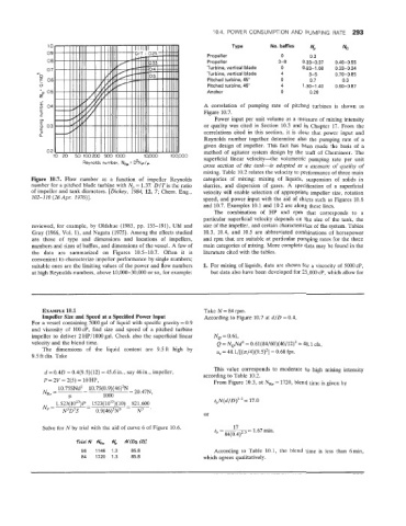
Reynolds number, NRe = D'Np/p
cross section of the tank-is adopted as a measure of quality of
mixing. Table 10.2 relates the velocity to performance of three main
-7. Flow number as a function of impeller Reynolds categories of mixing: mixing of liquids, suspension of solids in
number for a piitched blade turbine with Np = 1.37. D/T is the ratio slurries, and dispersion of gases. A specification of a superficial
of impeller and tank diameters. [Dickey, 1984, E, 7; Chem. Eng., velocity will enable selection of appropriate impeller size, rotation
102-110 (26Apr. 1976)]. speed, and power input with the aid of charts such as Figures 10.6
and 10.7. Examples 10.1 and 10.2 are along these lines.
The combination of HP and rpm that corresponds to a
particular superficial velocity depends on the size of the tank, the
reviewed, for example, by Qldshue (1983, pp. 155-191), Uhl and size of the impeller, and certain characteristics of the system. Tables
Gray (1966, Vol. I), and Nagata (1975). Among the effects studied 10.3, 10.4, and 10.5 are abbreviated combinations of horsepower
are those of type and dimensions and locations of impellers, and rpm that are suitable at particular pumping rates for the three
numbers and sizes of baffles, and dimensions of the vessel. A few of main categories of mixing. More complete data may be found in the
the data are summarized on Figures 10.5-10.7. Often it is literature cited with the tables.
convenient to characterize impeller performance by single numbers;
suitable ones are the limiting values of the power and flow numbers 1. For mixing of liquids, data are shown for a ~i~cocity 5000 cP,
of
at high Reynolds numbers, above 10,000-30,000 or so, for example: but data also have been developed for 25,000 cP, which allow for
EXAMPLE 1tO.1 Take N = 84 rpm.
Impeller Size and Speed at a Specified Power Input According to Figure 10.7 at d/D = 0.4,
For a vessel containing 5000 gal of liquid with specific gravity = 0.9
and viscosity of 1OOcP, find size and speed of a pitched turbine
impeller to deliver 2 NP/1000 gal. Check also the superficial linear NQ = 0.61,
velocity and the blend time. Q = NQNd3 = 0.61(84/60)(46/12)3 = 48.1 cfs,
The dimensions of the liquid content are 9.5ft high by us = 48.1/[(n/4)(9.5)'] = 0.68 fps.
9.5 ft dia. Take
This value corresponds to moderate to high mixing intensity
d = 0.40 = 0.4(9.5)(12) = 45.6 in., say 46 in., impeller, according to Table 10.2.
P = 2V = %(5) = 10 HP, From Figure 10.3, at N,, = 1720, blend time is given by
10.75SNd2 - 10.75(0.9)(46)'N := 20,47N,
NRe = -
I.1 1000
1.523(1013)P- 1523(1013)(10) - 821,600 tbN(d/D)Z.3 = 17.0
N --
'- NJDsS 0.9(46)'N3 N3
or
Solve for PIT by trial with the aid of curve 6 of Figure 10.6. t l7 1.67min.
- 84(0.4)2.3 -
Trial N he A', NIEq.(2)1
66 1146 1.3 85.8 According to Table 10.1, the blend time is less than 6min,
84 '1720 1.3 85.8 which agrees qualitatively.