
Page 331 - Chemical Process Equipment - Selection and Design
P. 331
10.5. SUSPENSION OF SOLIDS 295
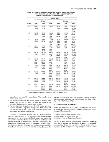
TABLE 10.3. Mixing of Liquids; Power and Impeller Speed (hp/rpm) for
Two Viscosities, as a Function of the Liquid Superficial
Velocity; Pitched Blade Turbine Impeller
Volume (gal)
5000 CP 25,000 CP
ftjsee 1000 2000 5000 1000 2000 5000
0.1 21280 2/190 2/100 21125 2/84 7.51125
1/190 1 /I 00 1.5184 1.5156 5/100
5/84
3/56
0.2 21190 21125 51125 3/84 511 25 10/84
l/lOO 2/84 3/84 2/84 3/84 7.5168
1.5184 3/68 1.5156 3/68 5/45
2/45 2/45 3/37
0.3 21125 3/84 7.51125 51125 1511 55 20/100
1.5/84 1.5156 51100 5/84 7.5168 15/68
5/84 3/68 5/45 10145
3/56 2/45 3/37 7.5137
0.4 2/84 511 25 10184 7.5184 10184 3011 00
1 .!si56 3/68 75/68 5/56 7.5/45 25/84
3/56 5/45 20/68
2/45 3/37 10137
0.5 51125 7.51125 1511 00 151155 251125 7511 90
3/84 5/84 10168 10/100 2011 00 6011 55
7.5145 10184 15/84 4011 00
7.5168 10156 15/45
0.6 511 00 1511 55 251125 2011 55 25/100 40184
3/68 10/1 00 20/100 1511 25 15/68 30168
3/56 7.5184 10156 15/56 25/56
2/45 3/37 7.5137 10145 20137
0.7 7.51125 10184 15/68 251155 4011 55 7511 25
5/84 7.5168 15/56 15/84 30/100 50184
5/45 10145 25/84 30145
10137 20168
0.8 101125 10168 3011 00 3011 55 5011 55 7511 00
7.5/100 7.5156 25/84 251125 4011 25 60184
20168 2011 00 50168
15/45 40156
0.9 1511 55 15/84 6011 55 401155 751190 75/84
10/100 10156 4011 00 301125 601155 60168
75/84 7.5145 251100 4011 00 50156
30168
7 .o 10184 3011 55 5011 00 4011 25 6011 25 1251125
75/68 2511 25 40184 30/100 5011 00 100/100
2011 00 30168 50184 75/68
15/68 25/56 40184 60/56
[Hicks, Morton, and Fenic, Chem. Eng., 102-110 (26 April 1976)I.
interpolation and possibly extrapolation. The impeller is a impeller and shaft must not rotate near their resonant frequency.
pitched-blade turbine. Such mechanical details are analyzed by Ramsey and Zoller [Chem.
2. For suspension of solids, the tables pertain to particles with Eng., 101-108 (30 Aug. 1976)].
settling velocities (of 10 ft/min, but data are available for
25 ft/min. The impeller is a pitched-blade turbine. 10.5. SUSPENSION OF SOLIDS
3. For gas dispersion the performance depends on the gas rate.
Data are shown for a superficial inlet gas rate of 0.07 ft/sec, but Besides the dimensions of the vessel, the impeller, and baffles,
data are available up to 0.2 ft/sec. Four baffles are specified and certain physical data are needed for complete description of a slurry
the impeller is a vertical blade turbine. mixing problem, primarily:
Example 1101.2 compares data of Table 10.4 with calculations 1. Specific gravities of the solid and liquid.
based on Figures, 10.6 and 10.7 for all-liquid mixing. Power and rpm 2. Solids content of the slurry (wt %).
requirements at a given superficial liquid velocity are seen to be 3. Settling velocity of the particles (ft/min).
very sensitive to impeller diameter. When alternate combinations of
IJP/rpm are shown in the table for a particular performance, the The last of these may be obtained from correlations when the
design of the agitator shaft may be a discriminant between them. mesh size or particle size distribution is known, or preferably
The shaft must allow far the torque and bending moment caused by experimentally. Taking into account these factors in their effect on
the hydraulic folrces acting on the impeller and shaft. Also, the suspension quality is at present a highly empirical process. Tables