
Page 333 - Chemical Process Equipment - Selection and Design
P. 333
30.6. GAS QISPERSION 297
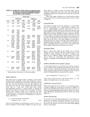
TABLE . Dispersion of Gases; Power and Impeller Speed power input as a factor is given by Treybal (Mass Transfer
(hr/r m) for Two Gas Inlet Superficial Velocities, Qperations, McGraw-Hill, New York, 1980, 156); presumably this
as a function of the Liquid Superficial Velocity;
Vefliical Blade Turbine lmpeller is applicable only below the minimum power input here represented
by Figure 10.11.
~~~
Volume (gal) When mass transfer coefficients are not determinable, agitator
design may be based on superficial liquid velocities with the criteria
0.07 ft/sec 0.20 ft/sec of Table 10.2.
ft/sec 1500 3000 5000 1500 3000 5000
--
0.1 2/56 5/84 7.5/68 3/56 75/68 10145 SYSTEM DESIGN
151155 10/100
0.2 2/45 7.51125 10184 3/45 1 511 55 15/68 The impeller commonly used for gas dispersion is a radial turbine
75/45 20/100 with six vertical blades. For a liquid height to diameter ratio
51100 10184 2511 25 h/D 5 1, a single impeller is adequate; in the range 1s h/D s 1.8
0.3 3/84 7.5168 10/45 7.5145 two are needed, and more than two are rarely used. The lower and
3/68 5/45 1 OJ55 upper impellers are located at distances of 1/6 and 2/3 of the liquid
3/56 7.5184 level above the bottom. Baffling is essential, commonly with four
5/56
0.4 51’1 25 10184 15/68 5/84 10145 3011 55 baffles of width 1/12 that of the tank diameter, offset from the wall
5/84 10/lOO 2011 00 7.51155 10156 20168 at 1/6 the width of the baffle and extending from the tangenat line of
5/100 10/45 15/84 5/56 15/45 the wall to the liquid level. The best position for inlet of the gas is
5/45 10156 20168 15/56 below and at the center of the lower impeller; an open pipe is
0.5 7.51125 151155 2511 25 7.511 25 15/68 25/84 commonly used, but a sparger often helps. Since ungassed power is
7.5 / 155 15/68 25/84 7.5168 15/84 2511 00 significantly larger than gassed, a two-speed motor is desirable to
75/68 15/84 25/100 7.5184 15/45 25/56 prevent overloading, the lower speed to cut in automatically when
75/84 15/45 25/56 15/56 the gas supply is interrupted and rotation still is needed.
0.6 10184 20/100 301155 10184 2011 00 3011 00
10/100 20168 3011 00 10/100 20168 3011 25
20145 30/125 3016% MINIMUM POWER
3016% 30145
0.7 t 0156 2511 25 4011 55 10156 2511 25 4011 55 Below a critical power input the gas bubbles are not affected
25/84 40184 25/84 40184 laterally but move upward with their natural buoyancy. This
25/100 4011 00 2511 00 40/100 condition is called gas flooding of the impeller. At higher power
25/56 40156 25/56 40156 inputs the gas is dispersed radially, bubbles impinge on the walls
0.8 1511 55 301155 5011 00 15/155 301155 5011 00 and are broken up, consequently with improvement of mass
15/84 30/100 50/68 15/84 3011 00 50168 transfer. A correlation of the critical power input is shown as Figure
3011 25 50184 3011 25 50184 10.10.
50145 50156
0.9 15/68 30168 601125 15/68 30168 6011 25
6011 55 6011 55 PQWER CONSUMPTION OF GASSED LIQUIDS
60184 60184
60/56 60156 At least partly because of its lower density and viscosity, the power
1 .o 20/100 4011 55 ?5/190 251125 401155 751190 to drive a mixture of gas and liquid is less than that to drive a liquid.
20168 40184 75/100 25/84 40184 751100 Figure 10.11(a) is a correlation of this effect, and other data at low
75/125 7511 25 values of the flow number Q/Nd3 are on Figure 10.11(b). The latter
[Hicks and Gatfs, Chern. Eng., 141-148 (19 July 197611. data for Newtonian fluids are correlated by the equation
P,/ P = 0.497(Q /Nd3)-0.38(N2d3p,/ (10.7)
MASS TRANSFER
where the last group of terms is the Weber number, pL is the
The starting point of agitator design is properly a mass transfer density of the liquid, and (T is its surface tension.
coefficient known empirically or from some correlation in terms of
parameters such as impeller size and rotation, power input, and gas
flow rate. Few such correlations are in the open literature, but SUPERFICIAL LIQUID VELOCITY
some have come from two of the industries that employ aerated When mass transfer data are not known or are not strictly pertinent,
stirred tanks on a large scale, namely liquid waste treating a quality of mixing may be selected by an exercise of judgment in
and fermentation processes. A favored method of studying the terms of the superficial liquid velocity on the basis of the rules of
absorption of oxygen is to measure the rate of oxidation of aqueous Table 10.2. For gas dispersion, this quantity is related to the power
sodium sulfite solutions. Figure 10.9 summarizes one such input, HP/1000 gal, the superficial gas velocity and the ratio d/D in
investigation of the effects of power input and gas rate on the mass Figure 10.12.
transfer coefficients. A correlation for fermentation air is given by
Dickey (1984, 12-17):
DESIGN PROCEDURES
k,a = rate/(cloncentration driving force) On the basis of the information gathered here, three methods are
= 0.064( f”,V )0.7ui2, 1 /sec, (10.6) possible for the design of agitated gas dispersion. In all cases the
size of the tank, the ratio of impeller and tank diameters and the
with P,/V in HP/”i000 gal and superficial gas velocity ug in ft/sec. A gas feed rate are specified. The data are for radial turbine impellers
general correlation of mass transfer coefficient that does not have with six vertical blades.