
Page 335 - Chemical Process Equipment - Selection and Design
P. 335
10.6. GAS DISPERSION 299
EXAMPLE 10.3 d/D and HP is read off Figure 10.8(d).
Design of the Agitation System for Maintenance of a Slurry
These conditions are taken: tip
V = 5000 gal, d/D Off btm Uniform
h/D = 1, 0.2 20 65
settling velocity = 10 ft/min, 0.4 7.5 25
0.6
4
12
solids content = 10 wt %
Reading from Fig,ure 10.8, Comparing with readings from Tables 10.2 and 10.3,
PI = 4, Superficial
F2 = 1.3, liq. velocity HP/rpm
3.0, off bottom, 0.3 (off btm) 10/45,10/56
10.0, uniform, 0.6 (uniform) 30/155,30/125,30/100,30/68
13.2, off bottom,
4 484 = {44, These results correspond roughly to those of the Oldshue
=
method at d/D = 0.4. The impeller sizes can be determined with
The relation between the ratio of impeller and vessel diameters, Figures 10.6 and 10.7.
Start with a known required mass transfer coefficient. From a 3. As soon as a superficial liquid velocity has been selected, a
correlation such as Figure 10.9 or Eq. (10.6) the gassed power suitable combination of HP/rpm can be taken from Table 10.5.
per unit volume will become known, and the total gassed power
to the tank will be Bg. The ratio of gassed power to ungassed These procedures are applied in Example 10.4.
power is represented by Figure 10.11(a) and the equations given As general rules, levels of 5-12HP/1000gal are typical of
there; at this :stage the rotation speed Ai is not yet known. This aerobic fermentation vessels, and 1-3 HP/1000 gal of aerobic waste
value is found by trial by simultaneous solution with Figure 10.6 treatment; concentrations and oxygen requirements of the
which relates ithe Reynolds and power numbers; the power here microorganisms are different in the two kinds of processes.
is the ungassed power. The value of N that results in the
precalculated Rg will be the correct one. Curve 2 of Figure 10.6 is
the one applicable to gas dispersion with the data of this section.
Start with a (choice of superficial liquid velocity uL made in
accordance with the criteria of Table 10.2. With the aid of the
known gas velocity us and d/D, find Pg/V from Figure 10.12.
Then proceed to find N by trial with Figures 10.11(a) and 10.6 as
in method 1.
0.1
KGO
.04
LE MOLES
FT3/HR/ATM . 02
. 0 I.
,006;
00'1
0.3 0.6 1.0 2.0 4.0 8.0 10 Superficiol qos velocity. fils
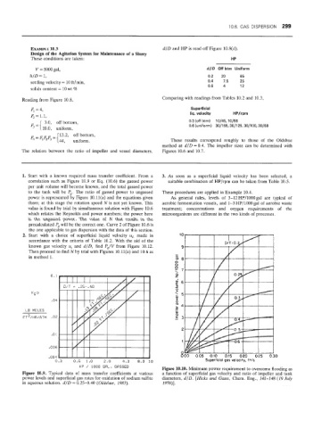
HP / 1000 GAL. GASSED Figure 10.10. Minimum power requirement to overcome flooding as
Figure 10.9. Typical data of mass transfer coefficients at various a function of superficial gas velocity and ratio of impeller and tank
power levels and superficial gas rates for oxidation of sodium sulfite diameters, d/D. [Hicks and Gates, Chem. Eng., 141-148 (19 July
in aqueous solution. d/D = 0.25-0.40 (Oldshue, 1983). 1976)].