Page 332 - Chemical Process Equipment - Selection and Design
P. 332

296  MIXING  AND  AGlTATiON
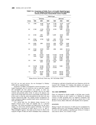
                                   TABLE 10.4. Suspension of Solids; Power and Impeller Speed (hp/rpm)
                                             for Two Settling Velocities, as a Function of the Superficial
                                              Velocity of the Liquid; Pitched Blade Turbine Impeller

                                                              Volume (gal)
                                                   10ft/min                 25ft/min
                                    ft/sec   1000    2000    5000     1000    2000    5000
                                     0.1    11190    211 90   51125   21190   211 25   51125
                                                     l/lOO   3/84     11190   2/84    3/84
                                                             3/68     1/100   1.5184   3/68
                                                             2/45            1.5156   2/45
                                     0.2    1/100    21125   7.51125   211 25   3/84   1511 55
                                                    1.5184   51100                    1011 00
                                                             5/84                     7.5168
                                                             3/56                     5/45
                                     0.3    21190    2/84    3/37    1.5184   51125   10184
                                                    1.5156                    3/68
                                                                              2/45
                                      0.4   21155    511 55   7.5184   2 /84   7.51155   7.5145
                                           1.51100           5/56    1.5156   51100
                                                                              3/56
                                      0.5   1.5184   3/84   1511 55   2/68   7.51125   15/84
                                            211 25          1011  00   2/56   5/84    10156
                                                             7.5168                  7.5137
                                                             5/45
                                      0.6   21100    51125   10184    3/84    5/56    2511 25
                                           1.5168    3/68                             2011  00
                                                     3/56                             15/68
                                                     2/45                             10145
                                      0.7   2/84    7.51155   15/84   7.51155   151155   301100
                                           1.5156   7.51125   10156   51125   10/100   25/84
                                                     5/84   7.5/45    51100   7.5184   20168
                                                            7.5137    3/68   7.5168   15/56
                                      0.8   3/84    7.5184   2511 25   7.51125   10184   6011 55
                                                     5/56   2011 00   5/84            4011  00
                                                             15/68                    30168
                                                             10145                    25/56
                                      0.9   7.51155   151155   4011 55   10/125   15/84   751190
                                            51125   10/100   3011  00   7.51100       601125
                                            51100   7.5168   25/84                    5011 00
                                            3/68            20168                     40184
                                      1 .o   7.51125   2011 00   50/1  00   1511 55   30/155   751125
                                            5/84    15/84   40184    1011  00   251125   751100
                                                    10184   30168            20/100   60184
                                                            25/56                     50184
                                       [Gates. Morton, and Fondy, Chem. Eng., 144-150 (24 May 1976)].


                10.2-10.5  are  one  such  process;  the  one  developed  by  Oldshue   of  horsepower and ratio of impeller and vessel diameters will do the
                (1983) will be examined shortly.                   required  task.  Example  10.3 employs  this  method,  and  makes  a
                   Suspension of  solids is maintained by upward movement of  the   comparison with the Chemineer method of  Tables 10.2 and 10.3.
                liquid. In principle, use of  a draft  tube  and an axial flow impeller
                will  accomplish  this  flow  pattern  most  readily.  It  turns  out,
                however,  that  such  arrangements  are  suitable only  for  low  solids   10.6.  GAS  DISPERSION
                contents and  moderate  power  levels. In order to be  effective, the
                cross section of  the draft tube must be appreciably smaller than that   Gases  are  dispersed  in  liquids usually  to  facilitate  mass  transfer
                of  the vessel, so that the solids concentration in the draft tube may   between  the  phases or mass  transfer  to  be  followed by  chemical
                become  impractically high.  The  usually practical arrangement  for   reaction.  In  some  situations  gases  are  dispersed  adequately with
                solids suspension employs a pitched blade turbine which gives both   spargers or porous distributors, but  the main concern here is with
                axial and radial flow.                              the more intense effects achievable with impeller driven agitators.
                   For  a  given  tank  size,  the  ultimate  design  objective  is  the
                relation  between  power  input  and  impeller  size  at  a  specified   SPARGERS
                uniformity. The factors governing such information  are  the  slurry
                volume, the slurry level, and the required uniformity. The method   Mixing of  liquids and suspension of  solids may be accomplished by
                of  Oldshue  has  corrections  for  these  factors,  as  Fl,  F,,  and  F3.   bubbling with  an inert  gas introduced uniformly at the  bottom  of
                When multiplied together,  they make up the factor F4 which is the   the tank.  For mild  agitation a superficial gas velocity of  1 ft/min is
                ordinate of Figure 10.8(d) and which determines what combinations   used, and for severe, one of  about 4 ft/min.
   327   328   329   330   331   332   333   334   335   336   337