
Page 124 - Chemical engineering design
P. 124
104
CHEMICAL ENGINEERING
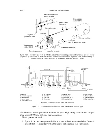
Ferrule wrapped with
insulating fibre
Process gas
outlet 550°C
Steam / Water
riser pipes
Alloy 800 ferrule
Concrete
Alloy 800
production plate
External insulation
Water downcomer pipes
Process gas
1200 / 1000°C Blowdown connection
Refractory concrete Insulating concrete
Figure 3.13. Reformed gas waste-heat boiler, principal features of typical natural circulation fire-tube boilers
(Reprinted by permission of the Council of the Institution of Mechanical Engineers from the Proceedings of
the Conference on Energy Recovery in the Process Industries, London, 1975.)
Air
To stack
1 From absorption
Secondary Air Air from tower no. 5
bleacher
4
3
Stream
6 7 13
5 .... 8 .... 9 11 14 15 16 17
....
....
Ammonia 2 10 12 To oxidation
tower
12 HNO 3 202 HNO 3 To absorption
Water Water
1. Air entry 6. Air preheater 10. Lamont boilers 14. Compressor
2. Ammonia vaporiser 7. Gas mixer 11. Steam drum 15. Steam turbine
3. Ammonia filter 8. Gas filters 12. Gas cooler No. 1 16. Heat exchanger
4. Control valves 9. Converters 13. Exhaust turbine 17. Gas cooler No. 2
5. Air-scrubbing tower
(From Nitric Acid Manufacture, Miles (1961), with permission)
Figure 3.14. Connections of a nitric acid plant, intermediate pressure type
distributed at a header pressure of around 8 bar (100 psig); so any reactor with a temper-
Ž
ature above 200 C is a potential steam generator.
Threesystems areused:
1. Figure 3.15a. An arrangement similar to a conventional water-tube boiler. Steam is
generated in cooling pipes within the reactor and separated in a steam drum.