Page 169 - Chemical engineering design
P. 169

146
                           output required (adiabatic) is the value that satisfies the conditions above. For a datum
                                          Ž
                           temperature of 25 C:         CHEMICAL ENGINEERING
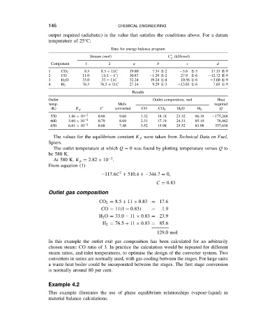
                                                     Data for energy-balance program
                                            Stream (mol)                     C ° (kJ/kmol)
                                                                              p
                            Component     1         2         a         b           c            d
                           1     CO 2     8.5    8.5 C 11C   19.80    7.34 E-2    5.6  E-5     17.15 E-9
                           2     CO      11.0    11 1   C    30.87    1.29 E-2    27.9  E-6   12.72 E-9
                           3     H 2 O   33.0    33   11C    32.24    l9.24 E-4   10.56 E-6    3.60 E-9
                           4     H 2     76.5    76.5 C 11C  27.14    9.29 E-3    13.81 E-6    7.65 E-9
                                                              Results
                           Outlet                                     Outlet composition, mol    Heat
                            temp.                       Mols                                    required
                            (K)        K p       C     converted  CO     CO 2   H 2 O    H 2      Q
                            550     1.86 ð 10  2  0.88   9.68    1.32   18.18   23.32   86.18   175,268
                            600    3.69 ð 10  2  0.79    8.69    2.31   17.19   24.31   85.19    76,462
                            650    6.61 ð 10  2  0.68    7.48    3.52   15.98   25.52   83.98   337,638

                             The values for the equilibrium constant K p were taken from Technical Data on Fuel,
                           Spiers.
                             The outlet temperature at which Q D 0 was found by plotting temperature versus Q to
                           be 580 K.
                                                     2
                             At 580 K, K p D 2.82 ð 10 .
                           From equation (1)
                                                         2
                                                  117.6C C 510.4 C 344.7 D 0,
                                                                        C D 0.83

                           Outlet gas composition
                                                CO 2 D 8.5 C 11 ð 0.83 D 17.6
                                                 CO D 11 1   0.83     D   1.9
                                                H 2 O D 33.0   11 ð 0.83 D 23.9
                                                  H 2 D 76.5 C 11 ð 0.83 D 85.6
                                                                        129.0 mol

                           In this example the outlet exit gas composition has been calculated for an arbitrarily
                           chosen steam: CO ratio of 3. In practice the calculation would be repeated for different
                           steam ratios, and inlet temperatures, to optimise the design of the converter system. Two
                           converters in series are normally used, with gas cooling between the stages. For large units
                           a waste-heat boiler could be incorporated between the stages. The first stage conversion
                           is normally around 80 per cent.


                           Example 4.2
                           This example illustrates the use of phase equilibrium relationships (vapour-liquid) in
                           material balance calculations.
   164   165   166   167   168   169   170   171   172   173   174