
Page 174 - Chemical engineering design
P. 174
FLOW-SHEETING
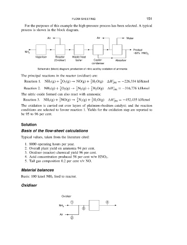
For the purposes of this example the high-pressure process has been selected. A typical
process is shown in the block diagram. 151
Air Air Water
Product
NH 3
~60% HNO 3
Vaporiser Reactor Waste heat
(Oxidiser) boiler Cooler- Absorber
condenser
Schematic (block) diagram; production of nitric acid by oxidation of ammonia
The principal reactions in the reactor (oxidiser) are:
3
5
Reaction 1. NH 3 (g) C O 2 (g) ! NO(g) C H 2 O(g) H Ž D 226,334 kJ/kmol
4 2 298
1
3
3
Reaction 2. NH 3 (g) C O 2 (g) ! N 2 (g) C H 2 O(g) H Ž D 316,776 kJ/kmol
4 2 2 298
The nitric oxide formed can also react with ammonia:
3
5
3
Reaction 3. NH 3 (g) C NO(g) ! N 2 (g) C H 2 O(g) H Ž D 452,435 kJ/kmol
2 4 2 298
The oxidation is carried out over layers of platinum-rhodium catalyst; and the reaction
conditions are selected to favour reaction 1. Yields for the oxidation step are reported to
be 95 to 96 per cent.
Solution
Basis of the flow-sheet calculations
Typical values, taken from the literature cited:
1. 8000 operating hours per year.
2. Overall plant yield on ammonia 94 per cent.
3. Oxidiser (reactor) chemical yield 96 per cent.
4. Acid concentration produced 58 per cent w/w HNO 3 .
5. Tail gas composition 0.2 per cent v/v NO.
Material balances
Basis: 100 kmol NH 3 feed to reactor.
Oxidiser
Oxidiser
1 4
NH 3
3
Air
2