
Page 218 - Chemical engineering design
P. 218
PIPING AND INSTRUMENTATION
the information can be shown clearly, without cluttering up the diagram. The service
connections to each unit should, however, be shown on the P and I diagram. 195
The P and I diagram will resemble the process flow-sheet, but the process
information is not shown. The same equipment identification numbers should be used
on both diagrams.
5.2.1. Symbols and layout
The symbols used to show the equipment, valves, instruments and control loops will
depend on the practice of the particular design office. The equipment symbols are usually
more detailed than those used for the process flow-sheet. A typical example of a P and I
diagram is shown in Figure 5.25.
Standard symbols for instruments, controllers and valves are given in the British
Standard BS 1646.
Austin (1979) gives a comprehensive summary of the British Standard symbols, and
also shows the American standard symbols (ANSI) and examples of those used by some
process plant contracting companies.
The German standard symbols are covered by DIN 28004, DIN (1988).
When laying out the diagram, it is only necessary to show the relative elevation of
the process connections to the equipment where these affect the process operation; for
example, the net positive suction head (NPSH) of pumps, barometric legs, syphons and
the operation of thermosyphon reboilers.
Computer aided drafting programs are available for the preparation of P and I diagrams,
see the reference to the PROCEDE package in Chapter 4.
5.2.2. Basic symbols
The symbols illustrated below are those given in BS 1646.
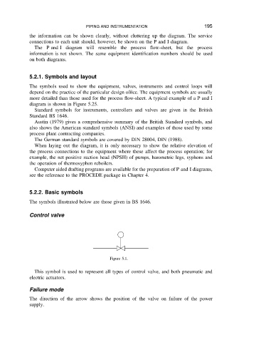
Control valve
Figure 5.1.
This symbol is used to represent all types of control valve, and both pneumatic and
electric actuators.
Failure mode
The direction of the arrow shows the position of the valve on failure of the power
supply.