Page 219 - Chemical engineering design
P. 219

196


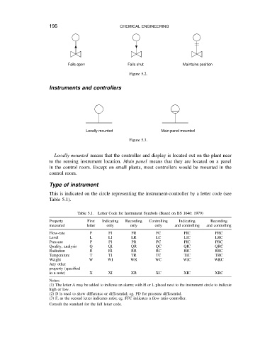
                                   Fails open           CHEMICAL ENGINEERING      Maintains position
                                                           Fails shut
                                                            Figure 5.2.


                           Instruments and controllers


                                          Locally mounted                Main panel mounted
                                                            Figure 5.3.


                             Locally mounted means that the controller and display is located out on the plant near
                           to the sensing instrument location. Main panel means that they are located on a panel
                           in the control room. Except on small plants, most controllers would be mounted in the
                           control room.

                           Type of instrument
                           This is indicated on the circle representing the instrument-controller by a letter code (see
                           Table 5.1).


                                       Table 5.1.  Letter Code for Instrument Symbols (Based on BS 1646: 1979)
                           Property        First  Indicating  Recording  Controlling  Indicating  Recording
                           measured        letter  only     only      only    and controlling  and controlling
                           Flow-rate        F      FI        FR        FC         FIC          FRC
                           Level            L      LI        LR        LC         LIC          LRC
                           Pressure         P      PI        PR        PC         PIC          PRC
                           Quality, analysis  Q    QI        QR        QC         QIC          QRC
                           Radiation        R      RI        RR        RC         RIC          RRC
                           Temperature      T      TI        TR        TC         TIC          TRC
                           Weight           W      WI       WR        WC          WIC         WRC
                           Any other
                           property (specified
                           in a note)       X      XI        XR        XC         XIC          XRC
                           Notes:
                           (1) The letter A may be added to indicate an alarm; with H or L placed next to the instrument circle to indicate
                           high or low.
                           (2) D is used to show difference or differential; eg. PD for pressure differential.
                           (3) F, as the second letter indicates ratio; eg. FFC indicates a flow ratio controller.
                           Consult the standard for the full letter code.
   214   215   216   217   218   219   220   221   222   223   224