
Page 253 - Chemical engineering design
P. 253
229
PIPING AND INSTRUMENTATION
4. Decide and show those ancillary instruments needed for the monitoring of the plant
operation by the operators; and for trouble-shooting and plant development. It is
well worthwhile including additional connections for instruments which may be
needed for future trouble-shooting and development, even if the instruments are not
installed permanently. This would include: extra thermowells, pressure tappings,
orifice flanges, and extra sample points.
5. Decide on the location of sample points.
6. Decide on the need for recorders and the location of the readout points, local or
control room. This step would be done in conjunction with steps 1 to 4.
7. Decide on the alarms and interlocks needed; this would be done in conjunction with
step 3 (see Chapter 9).
5.8. TYPICAL CONTROL SYSTEMS
5.8.1. Level control
In any equipment where an interface exists between two phases (e.g. liquid vapour),
some means of maintaining the interface at the required level must be provided. This
may be incorporated in the design of the equipment, as is usually done for decanters,
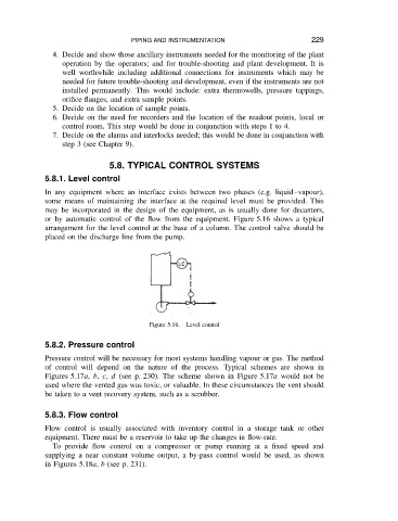
or by automatic control of the flow from the equipment. Figure 5.16 shows a typical
arrangement for the level control at the base of a column. The control valve should be
placed on the discharge line from the pump.
Figure 5.16. Level control
5.8.2. Pressure control
Pressure control will be necessary for most systems handling vapour or gas. The method
of control will depend on the nature of the process. Typical schemes are shown in
Figures 5.17a, b, c, d (see p. 230). The scheme shown in Figure 5.17a would not be
used where the vented gas was toxic, or valuable. In these circumstances the vent should
be taken to a vent recovery system, such as a scrubber.
5.8.3. Flow control
Flow control is usually associated with inventory control in a storage tank or other
equipment. There must be a reservoir to take up the changes in flow-rate.
To provide flow control on a compressor or pump running at a fixed speed and
supplying a near constant volume output, a by-pass control would be used, as shown
in Figures 5.18a, b (see p. 231).