
Page 279 - Chemical process engineering design and economics
P. 279
258 Chapter 5
Analysis
A simplified flow diagram for the process is shown in Figure 5.4.2. Table 5.4.1
list specifications for the process, obtained from Maddox and Burns [52, 53].
The shaft work for the pump will be calculated from Equation 5.48 and the shaft
power from Equation 5.49. Because the process at this point is not well defined,
all approximations must be made to maximize the estimated power so that the
pump will not be undersized.
First, designate the terminal points of the flow system. Point 1 is located
at the liquid surface at the bottom of the stripper, as shown in Figure 5.4.2. Point
2 is located at the top of the absorber. These points are selected because the
pressures, given in Table 5.4.1, are known.
Calculate the elevation on the discharge side of the pump - the first term in
Equation 5.48. The elevation consists of:
1. height of the column support, "the skirt"
2. the liquid level at the bottom of the absorber
3. distance between the liquid level and the gas inlet
4. the distance between the gas inlet and the bottom tray
5. the number of trays
6. distance between trays.
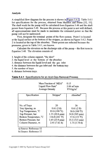
Table 5.4.1 Specifications for an Acid-Gas-Removal Process
Mass Fraction of MEA a 0.15
Liquid Flow Rate 2 2.08 nrVmin
Average Density 974 kg/m 3
Specification Stripper" Absorber 15
No. of Trays 20 26
Tray Spacing, m 0.61 (2 ft) 0.61 (2 ft)
Top Temperature, °C 93.0 (199 °F) 38.0 (100 °F)
Top Pressure, bar 1.35 (20.8 psia) 34.8 (505 psia)
Bottom Temperature, °C 116.0(241°F) 57.0 (135 °F)
Bottom Pressure, bar 1.65 (23 .9 psia) 35.5 (5 15 psia)
Column Diameter, m 2.41 (7.81 ft) 1.75 (5. 74 ft)
a) Source: Reference 52
b) Source: Reference 53
Copyright © 2003 by Taylor & Francis Group LLC