
Page 314 - Chemical process engineering design and economics
P. 314
Separator Design 293
move downward or upward toward the interface, depending on the specific gravity
of the two liquids. Then, at the interface, drops will accumulate before coalescing
with one of the phases.
To prevent entraining either the light or heavy phase in the outlet streams,
the liquid velocity in both outlet nozzles should be low. According to Jacobs and
Penny [17], the liquid velocity in each outlet nozzle should not be any more than
10 times the average velocity of each phase in the decanter. This rule allows siz-
ing the outlet nozzles.
If either a surface-active agent or a dispersion of fine solids is present, a
stable emulsion could form, which is analagous to foam in a gas-liquid system.
The emulsion or "rag" accumulates and will eventually have to be removed from
the decanter using valves located at the end of the vessel. After removal, the
emulsion can be de-emulsified by filtration, heating, adding chemical de-
emulsifying agents, or reversing the phase that is dispersed.
There appears to be no satisfactory sizing procedure for decanters. Drown
and Thomson [18] compared three sizing procedures and found that all were un-
satisfactory. We will develop a simple method here to illustrate some of the fac-
tors involved and to obtain a preliminary estimate of the decanter size. Accurate
sizing must be supplemented by testing. Even though settling and coalescing of
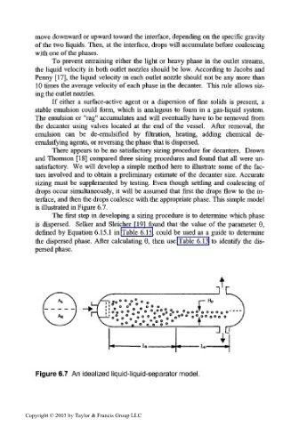
drops occur simultaneously, it will be assumed that first the drops flow to the in-
terface, and then the drops coalesce with the appropriate phase. This simple model
is illustrated in Figure 6.7.
The first step in developing a sizing procedure is to determine which phase
is dispersed. Selker and Sleicher [19] found that the value of the parameter 6,
defined by Equation 6.15.1 in Table 6.15, could be used as a guide to determine
the dispersed phase. After calculating 0, then use Table 6.13 to identify the dis-
persed phase.
J
i o°° ° ° o° t ° o r~ Hi>
' O O o O O o 4
T
! o o o ° o o o °o o0 0° °o o o „ o O O o o o o o
0
o ° o o » ° 0 o 0 0 0 » V ° 0 0 0 °
o° o° 0 0
".•.•.V.'S" t
H.D
Figure 6.7 An idealized liquid-liquid-separator model.
Copyright © 2003 by Taylor & Francis Group LLC