
Page 363 - Chemical process engineering design and economics
P. 363
342 Chapter 6
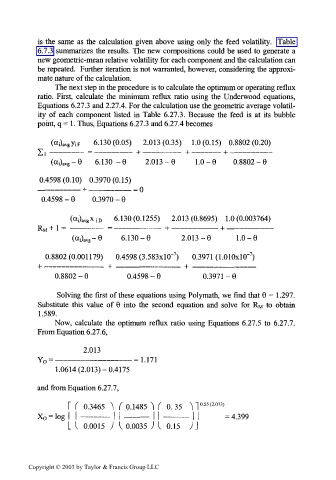
is the same as the calculation given above using only the feed volatility. Table
6.7.3 summarizes the results. The new compositions could be used to generate a
new geometric-mean relative volatility for each component and the calculation can
be repeated. Further iteration is not warranted, however, considering the approxi-
mate nature of the calculation.
The next step in the procedure is to calculate the optimum or operating reflux
ratio. First, calculate the minimum reflux ratio using the Underwood equations,
Equations 6.27.3 and 2.21 A. For the calculation use the geometric average volatil-
ity of each component listed in Table 6.27.3. Because the feed is at its bubble
point, q = 1. Thus, Equations 6.27.3 and 6.27.4 becomes
ViF 6.130(0.05) 2.013(0.35) 1.0(0.15) 0.8802(0.20)
(ccDavg-9 6.130-6 2.013-6 1.0-6 0.8802-9
0.4598(0.10) 0.3970(0.15)
——————— + ——————— = o
0.4598-9 0.3970-6
(oOavgXio 6.130(0.1255) 2.013(0.8695) 1.0(0.003764)
R M + 1 = ————— = ———————— + ———————— + ————————
(aOavg-6 6.130-6 2.013-6 1.0-6
7
7
0.8802 (0.001179) 0.4598 (3.583xlO~ ) 0.3971 (LOlOxlO" )
0.8802-6 0.4598-6 0.3971-9
Solving the first of these equations using Polymath, we find that 6=1.297.
Substitute this value of 6 into the second equation and solve for R M to obtain
1.589.
Now, calculate the optimum reflux ratio using Equations 6.27.5 to 6.27.7.
From Equation 6.27.6,
2.013
Y 0 = ————————————— =1.171
1.0614 (2.013)-0.4175
and from Equation 6.27.7,
55 2
T ( 0.3465 ^ ( 0.1485 ^( 0.35 ^ ] °- ( -°«>
L (. 0.0015 ) I 0.0035 ) I 0.15 )\
Copyright © 2003 by Taylor & Francis Group LLC