
Page 158 - Civil Engineering Formulas
P. 158
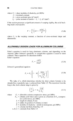
96                     CHAPTER THREE

           where G   shear modulus of elasticity, psi (MPa)
                J   torsional constant
                                         2
                                    2
                A   cross-sectional area, in (mm )
                                                   4
                                              4
                I p   polar moment of inertia   I x   I y , in (mm )
           If the section possesses a significant amount of warping rigidity, the axial buck-
           ling load is increased to
                                            2
                                   A
 EC w
                              P        GJ    2                  (3.28)
                                   I p      L
           where C w is the warping constant, a function of cross-sectional shape and
           dimensions.


           ALLOWABLE DESIGN LOADS FOR ALUMINUM COLUMNS

           Euler’s equation is used for long aluminum columns, and depending on the
           material, either Johnson’s parabolic or straight-line equation is used for short
           columns. These equations for aluminum follow
           Euler’s equation
                                          2
                                        c
 E
                                   F e                          (3.29)
                                        (L/ ) 2
           Johnson’s generalized equation


                        (3.30)
                                                  n
                                            (L/ )
                            F c   F ce 1   K  cE
                                            B F ce
             The value of n, which determines whether the short column formula is the
           straight-line or parabolic type, is selected from Table 3.5. The transition from the
           long to the short column range is given by
                                     cr
  kcE                 (3.31)
                                  L
                                          B F ce

           where   F e   allowable column compressive stress, psi (MPa)
                  F ce   column yield stress and is given as a function of F cy (compres-
                       sive yield stress), psi (MPa)
                    L   length of column, ft (m)
                       radius of gyration of column, in (mm)
                   E   modulus of elasticity—noted on nomograms, psi (MPa)
                    c   column-end fixity from Fig. 3.9
                n, K, k   constants from Table 3.5