
Page 154 - Civil Engineering Formulas
P. 154
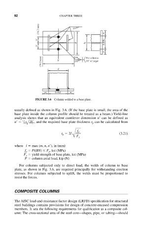
92                     CHAPTER THREE

                       (76.2 mm)         1/4            n


                       3"
                                          B    b f       0.80b f
                       3"
                                                        n
                        (76.2 mm)  N     1/4  2 2  For columns
                                               10" or larger
                                         1/4
                                 d


                          m    0.95d   m
                      FIGURE 3.6 Column welded to a base plate.


           usually defined as shown in Fig. 3.6. (If the base plate is small, the area of the
           base plate inside the column profile should be treated as a beam.) Yield-line
           analysis shows that an equivalent cantilever dimension n   can be defined as
               1
           n     42 dbf  , and the required base plate thickness t p can be calculated from

                                           f p
                                   t p   2l                     (3.21)
                                        B F y
           where l   max (m, n,  ), in (mm)
                            n
                f p   P/(BN)   F p , ksi (MPa)
                F y   yield strength of base plate, ksi (MPa)
                P   column axial load, kip (N)
             For columns subjected only to direct load, the welds of column to base
           plate, as shown in Fig. 3.6, are required principally for withstanding erection
           stresses. For columns subjected to uplift, the welds must be proportioned to
           resist the forces.


           COMPOSITE COLUMNS

           The AISC load-and-resistance factor design (LRFD) specification for structural
           steel buildings contains provisions for design of concrete-encased compression
           members. It sets the following requirements for qualification as a composite col-
           umn: The cross-sectional area of the steel core—shapes, pipe, or tubing—should