
Page 159 - Civil Engineering Formulas
P. 159
COLUMN FORMULAS 97
P P P
P P
Restraining bulk-
head partially
fixed
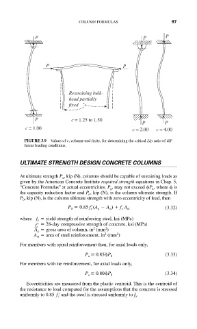
P c = 1.25 to 1.50
P P
c = 1.00 c = 2.00 c = 4.00
FIGURE 3.9 Values of c, column-end fixity, for determining the critical L/ ratio of dif-
ferent loading conditions.
ULTIMATE STRENGTH DESIGN CONCRETE COLUMNS
At ultimate strength P u , kip (N), columns should be capable of sustaining loads as
given by the American Concrete Institute required strength equations in Chap. 5,
“Concrete Formulas” at actual eccentricities. P u , may not exceed P n , where is
the capacity reduction factor and P n , kip (N), is the column ultimate strength. If
P 0 , kip (N), is the column ultimate strength with zero eccentricity of load, then
(3.32)
P 0 0.85 f c (A g A st ) f y A st
where f y yield strength of reinforcing steel, ksi (MPa)
f c 28-day compressive strength of concrete, ksi (MPa)
2
2
A g gross area of column, in (mm )
2
2
A st area of steel reinforcement, in (mm )
For members with spiral reinforcement then, for axial loads only,
(3.33)
P u 0.85 P 0
For members with tie reinforcement, for axial loads only,
(3.34)
P u 0.80 P 0
Eccentricities are measured from the plastic centroid. This is the centroid of
the resistance to load computed for the assumptions that the concrete is stressed
and the steel is stressed uniformly to f y .
uniformly to 0.85 f c