
Page 283 - Civil Engineering Formulas
P. 283
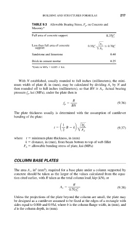
BUILDING AND STRUCTURES FORMULAS        217

                      TABLE 9.3 Allowable Bearing Stress, F , on Concrete and
                                                 p
                      Masonry*
                      Full area of concrete support         0.35f c


                      Less than full area of concrete  0.35f c    A 1    0.70f c
                        support
                                                       BA 2
                      Sandstone and limestone                 0.40
                      Brick in cement mortar                  0.25
                      *Units in MPa   6.895   ksi.


               With N established, usually rounded to full inches (millimeters), the mini-
             mum width of plate B, in (mm), may be calculated by dividing A by N and
                                                              1
             then rounded off to full inches (millimeters), so that BN   A . Actual bearing
                                                          1
             pressure f , ksi (MPa), under the plate then is
                    p
                                           R
                                      f p                         (9.36)
                                          BN
             The plate thickness usually is determined with the assumption of cantilever
             bending of the plate:
                                       1       3f p
                                 t    2  B   k  B F b             (9.37)

             where t   minimum plate thickness, in (mm)
                   k   distance, in (mm), from beam bottom to top of web fillet
                  F   allowable bending stress of plate, ksi (MPa)
                   b


             COLUMN BASE PLATES

                            2
                        2
             The area A , in (mm ), required for a base plate under a column supported by
                     1
             concrete should be taken as the larger of the values calculated from the equa-
             tion cited earlier, with R taken as the total column load, kip (kN), or
                                           R
                                    A 1                           (9.38)
                                         0.70 f c
             Unless the projections of the plate beyond the column are small, the plate may
             be designed as a cantilever assumed to be fixed at the edges of a rectangle with
             sides equal to 0.80b and 0.95d, where b is the column flange width, in (mm), and
             d is the column depth, in (mm).