Page 447 - Civil Engineering Formulas
P. 447

STORMWATER, WASTEWATER, AND ENVIRONMENTAL PROTECTION  373

             where R   recirculation ratio   Q /Q
                                      r
                 Q   recirculation flow
                   r
                  Q   wastewater flow
             The BOD loading for the first stage filter is calculated using
                    5
                       W   (influent BOD , mg/L)(wastewater flow, Mgd)
                                     5
             \               (8.34 lb/Mgal/mg/L)                 (13.49)
             The BOD loading for the second stage trickling filter is
                    5
                                   W   (1   E 1 )W               (13.50)
                           loading to the second stage filter.
             where W   BOD 5
               The NRC equation for a second stage trickling filter is
                                          100
                                E 2                              (13.51)
                                         0.0561  W
                                     1
                                         1   E 1 BVF
             The hydraulic loading to each filter is

                                             (1   R)(Q)
                           Hydraulic loading                     (13.52)
                                           (area)(1440 min/d)


             DESIGN OF A RAPID-MIX BASIN
             AND FLOCCULATION BASIN

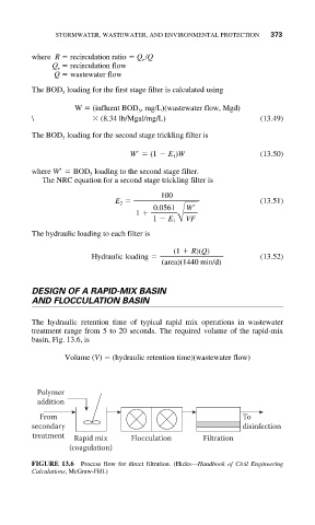
             The hydraulic retention time of typical rapid mix operations in wastewater
             treatment range from 5 to 20 seconds. The required volume of the rapid-mix
             basin, Fig. 13.6, is

                    Volume (V)   (hydraulic retention time)(wastewater flow)


              Polymer
              addition

               From                                          To
             secondary                                       disinfection
             treatment  Rapid mix   Flocculation    Filtration
                     (coagulation)
             FIGURE 13.6  Process flow for direct filtration. (Hicks—Handbook of Civil Engineering
             Calculations, McGraw-Hill.)
   442   443   444   445   446   447   448   449   450   451   452