Page 141 - Complementarity and Variational Inequalities in Electronics
P. 141

132  Complementarity and Variational Inequalities in Electronics


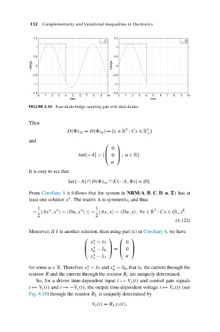
                           FIGURE 4.10 Four-diode-bridge sampling gate with ideal diodes.


                           Then
                                                                 3       4
                                          D( ) ∞ = D(  ∞ ) ={x ∈ R : Cx ∈ R }
                                                                         +
                           and
                                                        ⎛    ⎞
                                                           0
                                              ker{−A}={⎝ 0 ⎠ ; α ∈ R}.
                                                        ⎜
                                                             ⎟
                                                           α
                           It is easy to see that

                                          ker{−A}∩ D( ) ∞ ∩ K(−A, )}={0}.

                           From Corollary 8 it follows that the system in NRM(A,B,C,D,u, ) has at
                                          ∗
                           least one solution x . The matrix A is symmetric, and thus
                              1                      1                      3          4
                                               ∗
                                   ∗
                                      ∗
                            −  Ax ,x  −ÐDu,x  ≤−  Ax,x −ÐDu,x , ∀x ∈ R : Cx ∈ (R + ) .
                              2                      2
                                                                                    (4.122)
                           Moreover, if ¯x is another solution, then using part (c) in Corollary 8,wehave
                                                ⎛         ⎞   ⎛    ⎞
                                                    ∗
                                                   x −¯x 7       0
                                                    7
                                                    ∗
                                                ⎜         ⎟   ⎜    ⎟
                                                    6
                                                ⎝ x −¯x 6 ⎠ = ⎝ 0 ⎠
                                                    ∗            α
                                                   x −¯x 1
                                                    1
                                                            ∗
                           for some α ∈ R. Therefore x =¯x 7 and x =¯x 6 , that is, the current through the
                                                  ∗
                                                 7          6
                           resistor R and the current through the resistor R c are uniquely determined.
                              So, for a driven time-dependent input t  à  V s (t) and control gate signals
                           t  à  V c (t) and t  à −  V c (t), the output time-dependent voltage t  à  V o (t) (see
                           Fig. 4.10) through the resistor R L is uniquely determined by
                                                   V o (t) = R L x 7 (t),
   136   137   138   139   140   141   142   143   144   145   146