Page 147 - Complementarity and Variational Inequalities in Electronics
P. 147

138  Complementarity and Variational Inequalities in Electronics


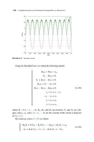
                           FIGURE 4.11 Rectifier circuit.


                              Using the Kirchhoff law, we obtain the following model:

                                            ⎧
                                                     R g i g + R 2 i 2 = u g ,
                                            ⎪
                                            ⎪
                                            ⎪
                                            ⎪
                                                       V E − R 2 i 2 = 0,
                                            ⎪
                                            ⎪
                                            ⎪
                                            ⎪
                                            ⎪
                                            ⎪
                                            ⎪
                                            ⎪
                                            ⎪   V C + R C i 5 − R 1 i 1 = 0,
                                            ⎪
                                            ⎪
                                            ⎪
                                            ⎪
                                            ⎪
                                            ⎪     R L i 4 + V C − V E = 0,
                                            ⎪
                                            ⎪
                                            ⎨
                                               R L i 4 − R C i 5 − R 6 i 6 = 0,     (4.128)
                                            ⎪
                                            ⎪
                                                          i g + i 3 = i 1 + i 2 ,
                                            ⎪
                                            ⎪
                                            ⎪
                                            ⎪
                                            ⎪
                                            ⎪
                                            ⎪
                                                        −i C − i E = i 3 ,
                                            ⎪
                                            ⎪
                                            ⎪
                                            ⎪
                                            ⎪
                                            ⎪
                                                          i 1 + i 5 = i 6 ,
                                            ⎪
                                            ⎪
                                            ⎪
                                            ⎪
                                            ⎪
                                            ⎪
                                                          i 4 + i 5 = i C ,
                                            ⎩
                           where R i > 0 (i = 1,...,6), R g , R C , and R L are resistors, V C and V E are volt-
                           ages, and i C , i E , and i i (i = 1,...,6) are the currents of the circuit as depicted
                           in Fig. 4.14.
                              By reducing system (4.128) we obtain
                                 ⎧
                                 ⎨  (R g K + N)V E − R g KV C =−R g i E + R g Si C + u g
                                                                                    (4.129)
                                    −(L + R 1 K)V E + (1 + L + R 1 K)V C =−Ti C ,
                                 ⎩
   142   143   144   145   146   147   148   149   150   151   152