
Page 15 - Complementarity and Variational Inequalities in Electronics
P. 15
The Complementarity Problem Chapter | 1 5
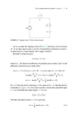
FIGURE 1.2 Clipping circuit 1: Diode as shunt element.
Let us consider the clipping circuit of Fig. 1.2 involving a load resistance
R> 0, an input signal source u and the corresponding instantaneous current i,
an ideal diode as a shunt element, and a supply voltage E.
Kirchoff’s voltage law gives
u = U R + V + E,
where U R = Ri denotes the difference of potential across resistor, and V is the
difference of potential across diode. Thus
0 ≤ i ⊥−V ≥ 0 ⇔ 0 ≤ i ⊥ E + Ri − u ≥ 0 ⇔ min{i,E − u + Ri}= 0
E − u E − u
⇔ min{i, + i}= 0 ⇔ i + min{0, }= 0
R R
E − u 1
⇔ i =−min{0, }= max{0,u − E}.
R R
If u ≤ E, then the diode is blocking (i = 0), whereas if u>E, then the diode is
1
conducting (i = (u − E)). Let us now consider a driven time-dependent input
R
t → u(t) and define the output signal t → V o (t) as
V o (t) = E + V(t).
The time-dependent current t → i(t) is given by
1
i(t) = max{0,u(t) − E}, (1.1)
R