
Page 188 - Complementarity and Variational Inequalities in Electronics
P. 188
The Nonregular Dynamical System Chapter | 5 179
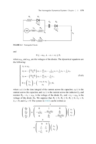
FIGURE 5.3 Nonregular Circuit.
and
⊥−x 3 + x 2 ≥ 0,
0 ≤−u D 1
are the voltages of the diodes. The dynamical equations are
where u D 4 and u D 1
the following:
⎧
⎪ ˙x 1 = x 2 ,
⎪
⎪
⎪
⎪
R 1 +R 3 R 1
⎪ 1 1 1
⎪ ˙x 2 =− x 2 + x 3 − x 1 + λ 1 + λ 2 ,
⎪
⎪ L 3 L 3 L 3 C 4 L 3 L 3
⎪
⎨
R 1 +R 2 R 1 1 (5.63)
˙ x 3 =− x 3 + x 2 − λ 1 ,
⎪ L 2 L 2 L 2
⎪
⎪
⎪
⎪
⎪
λ 1 −x 3 + x 2
⎪
⎪
⎪ 0 ≤ ⊥ ≥ 0,
⎪
⎩
λ 2 x 2
where x 1 (·) is the time integral of the current across the capacitor, x 2 (·) is the
current across the capacitor, and x 3 (·) is the current across the inductor L 2 and
is the
resistor R 2 , −λ 1 = u D 1 is the voltage of the diode D 1 , and −λ 2 = u D 4
voltage of the diode D 4 . We suppose that R 1 ≥ 0, R 2 ≥ 0, R 3 ≥ 0, L 2 > 0,
L 3 > 0, and C 4 > 0. The system in (5.63) can be written as
A
⎛ ⎞ ⎛ ⎞
dx 1 0 1 0 ⎛ ⎞
dt x 1
1 (R 1 +R 3 ) R 1
⎜ ⎟ ⎜ ⎟
⎜ dx 2 ⎟ = ⎜ − − ⎟⎝ x 2 ⎠
L 3 C 4 L 3 L 3
⎝ dt ⎠ ⎝ ⎠
0 −
dx 3 R 1 (R 1 +R 2 ) x 3
dt L 2 L 2
B
⎛ ⎞
0 0
1 1
⎜ ⎟ λ 1
+ ⎜ ⎟
L 3
⎝ L 3 ⎠
λ 2
1
− 0
L 2