
Page 101 - Complete Wireless Design
P. 101
Amplifier Design
100 Chapter Three
always be a little less than 1. However, even though the common-base ampli-
fier has superior temperature stability and linearity, and can easily operate at
very high frequencies, it is not nearly as common as the other two configura-
tions, the common-emitter and the common-collector amplifier. This is due
partly to the common-base amplifier’s low input impedance (50 to 75 ohms),
but these amplifiers can occasionally be found at the 50-ohm antenna input of
a receiver, or sometimes as Class C high-frequency amplifiers.
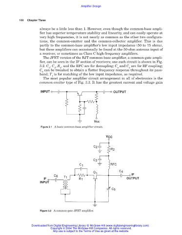
The JFET version of the BJT common-base amplifier, a common-gate ampli-
fier, can be seen in the IF section of receivers; one such circuit is shown in Fig.
3.2. C , C , R , and the RFC are for decoupling; C and C are for RF coupling;
2 3 2 4 6
C can be tweaked to obtain a flatter frequency response throughout its pass-
5
band; T is for matching of the low input impedance, as required.
1
The most popular amplifier circuit arrangement in all of electronics is the
common-emitter type of Fig. 3.3. It has the greatest current and voltage gain
Figure 3.1 A basic common-base amplifier circuit.
Figure 3.2 A common-gate JFET amplifier.
Downloaded from Digital Engineering Library @ McGraw-Hill (www.digitalengineeringlibrary.com)
Copyright © 2004 The McGraw-Hill Companies. All rights reserved.
Any use is subject to the Terms of Use as given at the website.