
Page 109 - Complete Wireless Design
P. 109
Amplifier Design
108 Chapter Three
MHz, with the most destructive frequencies being, of course, at 10.5 MHz and
11.1 MHz. This is well within the passband of this particular receiver. Much
higher order IMD is created in receivers and amplifiers, so all IMD up to the
seventh order should be accounted for and, if it does fall within band, must be
at such a low amplitude that it cannot cause problems.
A low return loss (a high VSWR) can also create IMD in an amplifier or mix-
er stage because of the reflected waves from the next stage returning and mix-
ing with the output and its sidebands.
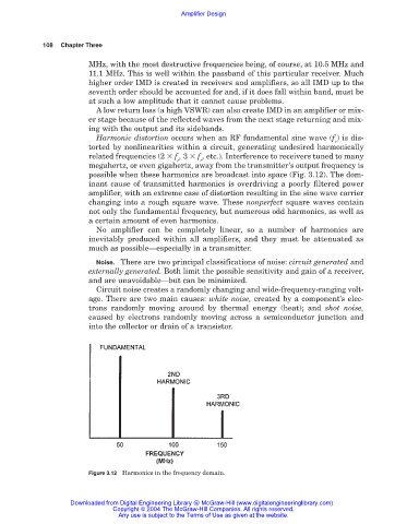
Harmonic distortion occurs when an RF fundamental sine wave (f ) is dis-
r
torted by nonlinearities within a circuit, generating undesired harmonically
related frequencies (2 f , 3 f , etc.). Interference to receivers tuned to many
r r
megahertz, or even gigahertz, away from the transmitter’s output frequency is
possible when these harmonics are broadcast into space (Fig. 3.12). The dom-
inant cause of transmitted harmonics is overdriving a poorly filtered power
amplifier, with an extreme case of distortion resulting in the sine wave carrier
changing into a rough square wave. These nonperfect square waves contain
not only the fundamental frequency, but numerous odd harmonics, as well as
a certain amount of even harmonics.
No amplifier can be completely linear, so a number of harmonics are
inevitably produced within all amplifiers, and they must be attenuated as
much as possible—especially in a transmitter.
Noise. There are two principal classifications of noise: circuit generated and
externally generated. Both limit the possible sensitivity and gain of a receiver,
and are unavoidable—but can be minimized.
Circuit noise creates a randomly changing and wide-frequency-ranging volt-
age. There are two main causes: white noise, created by a component’s elec-
trons randomly moving around by thermal energy (heat); and shot noise,
caused by electrons randomly moving across a semiconductor junction and
into the collector or drain of a transistor.
Figure 3.12 Harmonics in the frequency domain.
Downloaded from Digital Engineering Library @ McGraw-Hill (www.digitalengineeringlibrary.com)
Copyright © 2004 The McGraw-Hill Companies. All rights reserved.
Any use is subject to the Terms of Use as given at the website.