
Page 114 - Complete Wireless Design
P. 114
Amplifier Design
Amplifier Design 113
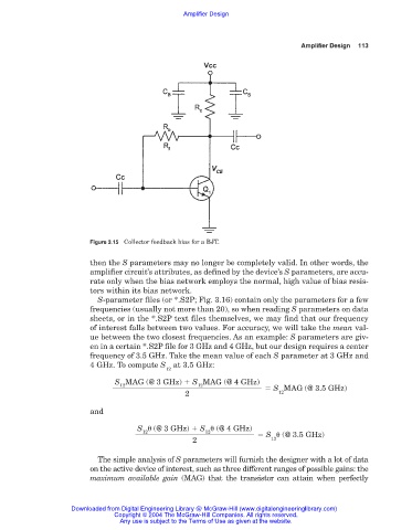
Figure 3.15 Collector feedback bias for a BJT.
then the S parameters may no longer be completely valid. In other words, the
amplifier circuit’s attributes, as defined by the device’s S parameters, are accu-
rate only when the bias network employs the normal, high value of bias resis-
tors within its bias network.
S-parameter files (or *.S2P; Fig. 3.16) contain only the parameters for a few
frequencies (usually not more than 20), so when reading S parameters on data
sheets, or in the *.S2P text files themselves, we may find that our frequency
of interest falls between two values. For accuracy, we will take the mean val-
ue between the two closest frequencies. As an example: S parameters are giv-
en in a certain *.S2P file for 3 GHz and 4 GHz, but our design requires a center
frequency of 3.5 GHz. Take the mean value of each S parameter at 3 GHz and
4 GHz. To compute S at 3.5 GHz:
12
S MAG (@ 3 GHz) S MAG (@ 4 GHz)
12
12
S MAG (@ 3.5 GHz)
2 12
and
S (@ 3 GHz) S (@ 4 GHz)
12
12
S (@ 3.5 GHz)
2 12
The simple analysis of S parameters will furnish the designer with a lot of data
on the active device of interest, such as three different ranges of possible gains: the
maximum available gain (MAG) that the transistor can attain when perfectly
Downloaded from Digital Engineering Library @ McGraw-Hill (www.digitalengineeringlibrary.com)
Copyright © 2004 The McGraw-Hill Companies. All rights reserved.
Any use is subject to the Terms of Use as given at the website.