
Page 115 - Complete Wireless Design
P. 115
Amplifier Design
114 Chapter Three
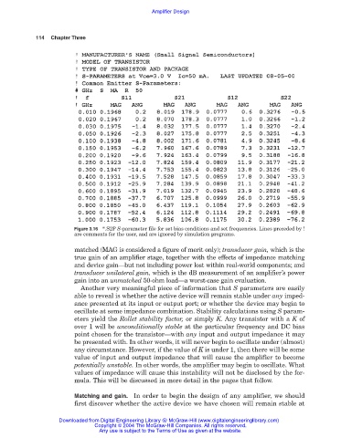
Figure 3.16 *.S2P S-parameter file for set bias conditions and set frequencies. Lines preceded by !
are comments for the user, and are ignored by simulation programs.
matched (MAG is considered a figure of merit only); transducer gain, which is the
true gain of an amplifier stage, together with the effects of impedance matching
and device gain—but not including power lost within real-world components; and
transducer unilateral gain, which is the dB measurement of an amplifier’s power
gain into an unmatched 50-ohm load—a worst-case gain evaluation.
Another very meaningful piece of information that S parameters are easily
able to reveal is whether the active device will remain stable under any imped-
ance presented at its input or output port; or whether the device may begin to
oscillate at some impedance combination. Stability calculations using S param-
eters yield the Rollet stability factor, or simply K. Any transistor with a K of
over 1 will be unconditionally stable at the particular frequency and DC bias
point chosen for the transistor—with any input and output impedance it may
be presented with. In other words, it will never begin to oscillate under (almost)
any circumstance. However, if the value of K is under 1, then there will be some
value of input and output impedance that will cause the amplifier to become
potentially unstable. In other words, the amplifier may begin to oscillate. What
values of impedance will cause this instability will not be disclosed by the for-
mula. This will be discussed in more detail in the pages that follow.
Matching and gain. In order to begin the design of any amplifier, we should
first discover whether the active device we have chosen will remain stable at
Downloaded from Digital Engineering Library @ McGraw-Hill (www.digitalengineeringlibrary.com)
Copyright © 2004 The McGraw-Hill Companies. All rights reserved.
Any use is subject to the Terms of Use as given at the website.