
Page 238 - Complete Wireless Design
P. 238
Oscillator Design
Oscillator Design 237
4. Tapping the oscillator’s output with a high-reactance capacitor or inductor
(50 to 200 ohms for a BJT) into a 50-ohm 6-dB pad will supply low output
power, good phase noise, and a medium 50-ohm match at the pad’s output.
During the simulation stage, always attach the oscillator’s load (normally 50
ohms), and its output coupling reactance (normally C ), to the oscillator’s
COUP
output as a final test that the open-loop gain will not be degraded excessively
by the inclusion of this load. Attach the Bode plotter’s input between the tran-
sistor’s collector and C , and not between C and the oscillator’s load.
COUP COUP
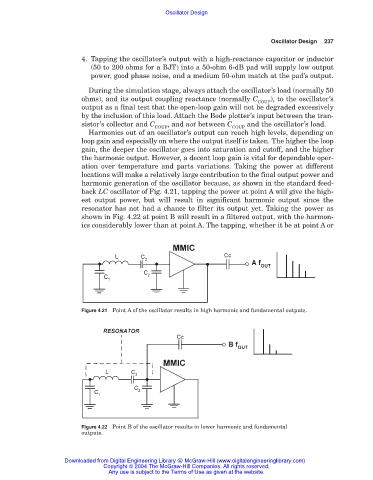
Harmonics out of an oscillator’s output can reach high levels, depending on
loop gain and especially on where the output itself is taken. The higher the loop
gain, the deeper the oscillator goes into saturation and cutoff, and the higher
the harmonic output. However, a decent loop gain is vital for dependable oper-
ation over temperature and parts variations. Taking the power at different
locations will make a relatively large contribution to the final output power and
harmonic generation of the oscillator because, as shown in the standard feed-
back LC oscillator of Fig. 4.21, tapping the power at point A will give the high-
est output power, but will result in significant harmonic output since the
resonator has not had a chance to filter its output yet. Taking the power as
shown in Fig. 4.22 at point B will result in a filtered output, with the harmon-
ics considerably lower than at point A. The tapping, whether it be at point A or
Figure 4.21 Point A of the oscillator results in high harmonic and fundamental outputs.
Figure 4.22 Point B of the oscillator results in lower harmonic and fundamental
outputs.
Downloaded from Digital Engineering Library @ McGraw-Hill (www.digitalengineeringlibrary.com)
Copyright © 2004 The McGraw-Hill Companies. All rights reserved.
Any use is subject to the Terms of Use as given at the website.