
Page 235 - Complete Wireless Design
P. 235
Oscillator Design
234 Chapter Four
With the proper wide tuning varactor for D , a tuning bandwidth of 100 percent can
1
be accomplished by employing a 10-to-1 capacitance hyperabrupt varactor, along
with the proper tuning voltage range for V . However, when the VCO is used in
CNTRL
this wideband mode, its output power will begin to decrease as the f increases.
OUT
This is not a problem in less demanding VCO applications, or in a more narrowband
( 50 percent tuning range) mode.
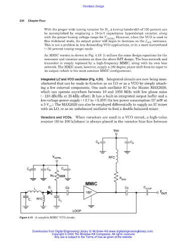
An MMIC version is shown in Fig. 4.19. It utilizes the same design equations for the
resonator and varactor sections as does the above BJT design. The bias network and
transistor is simply replaced by a high-frequency MMIC, along with its own bias
network. The MMIC must, however, supply a 180 degree phase shift from its input to
its output (which is the most common MMIC configuration).
Integrated LC and VCO oscillator (Fig. 4.20). Integrated circuits are now being man-
ufactured that can be made to function as an LO or as a VCO by simply attach-
ing a few external components. One such oscillator IC is the Maxim MAX2620,
which can operate anywhere between 10 and 1050 MHz with low phase noise
( 110 dBc/Hz at 25-kHz offset). It has a built-in integrated output buffer and a
low-voltage power supply ( 2.7 to 5.25V) for low power consumption (27 mW at
a 3-V ). The MAX2620 can also be employed differentially to supply an IC mixer
CC
with an LO, or as an unbalanced oscillator to feed a double-balanced mixer.
Varactors and VCOs. When varactors are used in a VCO circuit, a high-value
resistor (50 to 100 kilohms) is always placed in the varactor bias line between
Figure 4.19 A complete MMIC VCO circuit.
Downloaded from Digital Engineering Library @ McGraw-Hill (www.digitalengineeringlibrary.com)
Copyright © 2004 The McGraw-Hill Companies. All rights reserved.
Any use is subject to the Terms of Use as given at the website.