
Page 231 - Complete Wireless Design
P. 231
Oscillator Design
230 Chapter Four
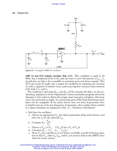
Figure 4.16 A complete MMIC LC oscillator.
JFET LC and VCO Colpitts oscillator (Fig. 4.17). This oscillator is good to 50
MHz, has a loaded Q of 20 to 25, and can tune to over 100 percent of f . L
OUT 1
should give as high a Q as possible to maximize gain and phase margin. This
VCO can easily be made into a simple LC oscillator by replacing the varactor
D with a capacitor of similar value, and removing the varactor’s bias network
1
of R, both C ’s, and L .
c 2
The oscillator’s open-loop Z and Z will be around 150 ohms, so the ter-
OUT IN
minating impedances of the S-parameter linear simulation program should be
changed to this value to obtain the proper open-loop gain and phase. However,
when the mismatch is slight, the actual loop gain of the final closed-loop oscil-
lator will be negligible. If the active device does not have S-parameter files
available because of its low frequency of operation, then employ Spice models
in a Spice simulator as explained in Sec. 4.1, “Oscillator Simulation.”
1. Self-bias the oscillator.
a. Choose an appropriate V for Class A operation of the active device, and
GS
note the I for the selected V .
D GS
V
GS
b. Compute R .
S
I
D
c. Choose a V of (V 2 V )/2 for a V of V /2.
DS dd GS d dd
d. Calculate R (V V V /I ).
d dd ds GS d
e. Since V for a specific I is not always available, use the following equa-
GS D
tion to find V when I , I , and V are known (look in the JFET’s data
GS D DSS P
sheet for these values):
Downloaded from Digital Engineering Library @ McGraw-Hill (www.digitalengineeringlibrary.com)
Copyright © 2004 The McGraw-Hill Companies. All rights reserved.
Any use is subject to the Terms of Use as given at the website.