
Page 228 - Complete Wireless Design
P. 228
Oscillator Design
Oscillator Design 227
decrease formation of distortion products. However, this cuts the varactor
capacitance values in half.
There are two different types of varactor diodes utilized in VCO circuits. The
abrupt form has a very high Q (and thus low phase noise), and can take a wide
voltage tuning range (up to 0 to 55 V) to travel through the full range of capac-
itance values, meaning that abrupt diodes possess low tuning sensitivity.
Abrupt diodes also have a low capacitance range, but with low distortion char-
acteristics. The hyperabrupt varactor type, on the other hand, has a complete
tuning range of 0 to 20 V for increased sensitivity, so it is the varactor of choice
for wideband applications. However, it has a lower Q, and thus more phase
noise, than the abrupt type.
Both varactor types may have a 0 V capacitance specification, but because
of nonlinearity and Q problems, at least 0.1 V should always be across any var-
actor—and sometimes more.
4.2.3 Designing LC oscillators and VCOs
Designing LC oscillators and VCOs with the following procedures, while veri-
fying their operation as described in Sec. 4.1, “Oscillator Simulation,” will per-
mit the engineer to design and build stable and reliable circuits for a variety
of requirements.
LC BJT oscillator design (Fig. 4.15). This oscillator will function reliably up to
500 MHz.
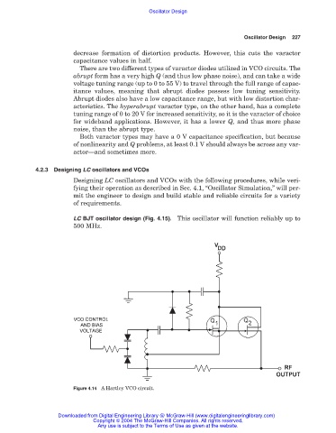
Figure 4.14 A Hartley VCO circuit.
Downloaded from Digital Engineering Library @ McGraw-Hill (www.digitalengineeringlibrary.com)
Copyright © 2004 The McGraw-Hill Companies. All rights reserved.
Any use is subject to the Terms of Use as given at the website.