
Page 223 - Complete Wireless Design
P. 223
Oscillator Design
222 Chapter Four
with higher transistor bias current we can also decrease the phase noise, since
the carrier will now be at a higher relative amplitude above this noise.
As open-loop oscillator design accuracy depends on both ends of the oscillator
loop being at the same impedance (as well as both terminating impedances in
the linear simulator being equal), then it can be seen that ignoring cascaded
input and output impedances will result in a nonoptimized oscillator design.
However, a new technique that allows the oscillator designer to not have so
much dependence on the oscillator’s terminating impedances with the linear
simulator for an accurate prediction of the oscillator’s gain and phase has just
been recently presented. This new technique employs Harada’s equations, and
assumes that S equals zero, which is never the case. Therefore, it is recom-
12
mended that for ease of computations, and for very acceptable accuracy, that
normal open-loop analysis (as demonstrated by Rhea) should be followed for the
design of most oscillators.
In utilizing open-loop oscillator design, it is assumed that the open loop is
stable. In other words, the amplifier section (with bias) should not be unsta-
ble, since it is only when the loop is closed from input to output that oscilla-
tions are meant to occur. Proper frequency stability may become quite erratic
with an unstable device, so choose only unconditionally stable transistors.
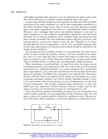
When simulating a crystal oscillator, we must first select the proper crystal
by obtaining certain crystal parameters (Fig. 4.9), such as the crystal’s motional
capacitance (C ), motional inductance (L ), series resistance (R ), and parallel
M M M
plate capacitance (C or C ) from the manufacturer for the crystal’s desired fre-
P 0
quency of operation, its holder type, and quartz cut (typically AT). The manu-
facturer will also need to be informed if the crystal is to be utilized in a series
or parallel resonance oscillator (see “Pierce Crystal Oscillator Design” in Sec.
4.3.3), and whether the crystal is being run on its fundamental or on one of its
overtone frequencies. The crystal’s required aging specification in parts per
million per year (ppm/year), initial frequency accuracy in ppm, and the fre-
quency accuracy over temperature in ppm are all important as well.
Since many linear computer simulation packages may not necessarily have
crystal models available, we must model the crystal as shown in Fig. 4.9, and
place it where the crystal would be within the oscillator circuit. This equiva-
lent LCR model, while simplistic, is more than adequate to realistically repre-
Figure 4.9 Equivalent internal structure of a crystal.
Downloaded from Digital Engineering Library @ McGraw-Hill (www.digitalengineeringlibrary.com)
Copyright © 2004 The McGraw-Hill Companies. All rights reserved.
Any use is subject to the Terms of Use as given at the website.