
Page 222 - Complete Wireless Design
P. 222
Oscillator Design
Oscillator Design 221
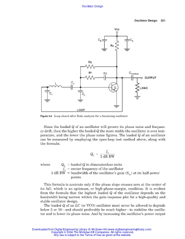
Figure 4.8 Loop closed after Bode analysis for a functionig oscillator.
Since the loaded Q of an oscillator will govern its phase noise and frequen-
cy drift, then the higher the loaded Q the more stable the oscillator is over tem-
perature, and the lower the phase noise figures. The loaded Q of an oscillator
can be measured by employing the open-loop test method above, along with
the formula:
f
0
Q
L
3 dB BW
where Q loaded Q in dimensionless units
L
f center frequency of the oscillator
0
3 dB BW bandwidth of the oscillator’s gain (S ) at its half-power
21
points
This formula is accurate only if the phase slope crosses zero at the center of
its fall, which is an optimum, or high-phase-margin, condition. It is evident
from the formula that the highest loaded Q of the oscillator depends on the
bandwidth being narrow within the gain response plot for a high-quality and
stable oscillator design.
The loaded Q of an LC (or VCO) oscillator must never be allowed to degrade
below 5 or 10—and should preferably be much higher—to stabilize the oscilla-
tor and to lower its phase noise. And by increasing the oscillator’s power output
Downloaded from Digital Engineering Library @ McGraw-Hill (www.digitalengineeringlibrary.com)
Copyright © 2004 The McGraw-Hill Companies. All rights reserved.
Any use is subject to the Terms of Use as given at the website.