
Page 227 - Complete Wireless Design
P. 227
Oscillator Design
226 Chapter Four
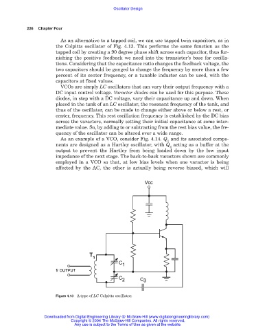
As an alternative to a tapped coil, we can use tapped twin capacitors, as in
the Colpitts oscillator of Fig. 4.13. This performs the same function as the
tapped coil by creating a 90 degree phase shift across each capacitor, thus fur-
nishing the positive feedback we need into the transistor’s base for oscilla-
tions. Considering that the capacitance ratio changes the feedback voltage, the
two capacitors should be ganged to change the frequency by more than a few
percent of its center frequency, or a tunable inductor can be used, with the
capacitors at fixed values.
VCOs are simply LC oscillators that can vary their output frequency with a
DC input control voltage. Varactor diodes can be used for this purpose. These
diodes, in step with a DC voltage, vary their capacitance up and down. When
placed in the tank of an LC oscillator, the resonant frequency of the tank, and
thus of the oscillator, can be made to change either above or below a rest, or
center, frequency. This rest oscillation frequency is established by the DC bias
across the varactors, normally setting their initial capacitance at some inter-
mediate value. So, by adding to or subtracting from the rest bias value, the fre-
quency of the oscillator can be altered over a wide range.
As an example of a VCO, consider Fig. 4.14. Q and its associated compo-
1
nents are designed as a Hartley oscillator, with Q acting as a buffer at the
2
output to prevent the Hartley from being loaded down by the low input
impedance of the next stage. The back-to-back varactors shown are commonly
employed in a VCO so that, at low bias levels when one varactor is being
affected by the AC, the other is actually being reverse biased, which will
Figure 4.13 A type of LC Colpitts oscillator.
Downloaded from Digital Engineering Library @ McGraw-Hill (www.digitalengineeringlibrary.com)
Copyright © 2004 The McGraw-Hill Companies. All rights reserved.
Any use is subject to the Terms of Use as given at the website.