
Page 226 - Complete Wireless Design
P. 226
Oscillator Design
Oscillator Design 225
and C block the DC, but couple the AC feedback, while L and C decouple the
3 2 6
oscillator output, preventing it from being injected into the power supply. L also
2
functions as the transistor’s collector load, and R and R supply the forward
1 2
bias. R and C further increase the temperature stability of this circuit without
E 4
allowing the AC gain to be decreased, as it would be if just R were used.
E
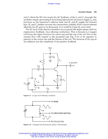
The LC tank of the Hartley furnishes the required 180 degree phase shift for
regenerative feedback, thus allowing oscillations. This is because L ’s tapped
1
coil forces the signal between the center tap and the top of the coil (due to the
current flow with respect to the grounded tap; Fig. 4.12) to be opposite in
polarity to the center tap and the bottom of the coil. The location of the tap on
the inductor sets the amplitude of the positive feedback.
Figure 4.11 A type of LC Hartley oscillator.
Figure 4.12 A tapped coil showing the phase relationships.
Downloaded from Digital Engineering Library @ McGraw-Hill (www.digitalengineeringlibrary.com)
Copyright © 2004 The McGraw-Hill Companies. All rights reserved.
Any use is subject to the Terms of Use as given at the website.