
Page 219 - Complete Wireless Design
P. 219
Oscillator Design
218 Chapter Four
display itself will be exhibited as a separate graphical window within the pro-
gram. In using the Bode tool—by injecting a signal into the oscillator’s input
and checking the phase and gain at the oscillator’s output—we will have a
very good indication that our design is valid. This is accomplished, as
described above, by breaking the feedback loop of the oscillator and attaching
the Bode plotter between the broken input/output points of the oscillator. To
obtain a proper reading, set the frequency and phase of the Bode plotter to a
linear scale, adjust the magnitude to display a gain of 20 to 20 dB (or, if
need be, higher values), set the display to show phase values from 180 to
180 degrees (Fig. 4.5), and adjust the frequency sweep to approximately ±25
percent of the expected oscillation frequency (narrow or widen as necessary to
obtain the display as shown in the figure). This open-loop Bode response test
is a good indication that the oscillator will oscillate and function as intended,
since the Bode plotter is outputting a 0 degree phase angle signal at the fre-
quencies of interest into the input of the oscillator’s resonator, which changes
its phase by 180 degrees before it reaches the input of the transistor; the tran-
sistor, being in common-emitter configuration, changes it another 180
degrees, making for a phase change of 360, or 0, degrees, for regenerative
oscillatory feedback. The proper phase change, at the appropriate amplitude,
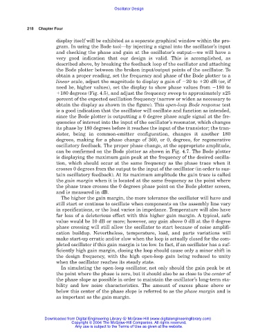
can be confirmed on the Bode plotter as shown in Fig. 4.7. The Bode plotter
is displaying the maximum gain peak at the frequency of the desired oscilla-
tion, which should occur at the same frequency as the phase trace when it
crosses 0 degrees from the output to the input of the oscillator (in order to sus-
tain oscillatory feedback). At its maximum amplitude the gain trace is called
the gain margin when it is located at the same frequency as the point where
the phase trace crosses the 0 degrees phase point on the Bode plotter screen,
and is measured in dB.
The higher the gain margin, the more tolerance the oscillator will have and
still start or continue to oscillate when components on the assembly line vary
in specifications, or the load varies in impedance. Temperature will also have
far less of a deleterious effect with this higher gain margin. A typical, safe
value would be 10 dB or more; however, any gain above 0 dB at the 0 degree
phase crossing will still allow the oscillator to start because of noise amplifi-
cation buildup. Nevertheless, temperature, load, and parts variations will
make start-up erratic and/or slow when the loop is actually closed for the com-
pleted oscillator if this gain margin is too low. In fact, if an oscillator has a suf-
ficiently high gain margin, closing the loop should cause only a minor shift in
the design frequency, with the high open-loop gain being reduced to unity
when the oscillator reaches its steady state.
In simulating the open-loop oscillator, not only should the gain peak be at
the point where the phase is zero, but it should also be as close to the center of
the phase slope as possible in order to maintain the oscillator’s long-term sta-
bility and low noise characteristics. The amount of excess phase above or
below this center of the phase slope is referred to as the phase margin and is
as important as the gain margin.
Downloaded from Digital Engineering Library @ McGraw-Hill (www.digitalengineeringlibrary.com)
Copyright © 2004 The McGraw-Hill Companies. All rights reserved.
Any use is subject to the Terms of Use as given at the website.