
Page 215 - Complete Wireless Design
P. 215
Oscillator Design
214 Chapter Four
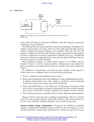
Figure 4.1 A damped sine-wave output of a tuned tank after insertion of a
single pulse.
input. This will create a continuous oscillation, with the transistor constantly
amplifying its own feedback.
Considering that the typical oscillator functions by feeding a 180 degree out-
of-phase signal back to its input, with the phase shift caused by the common-
emitter configuration of the oscillator’s own amplifier (Fig. 4.2), then we will
require a method to shift this out-of-phase output signal back to zero degrees
in order to obtain the necessary regenerative feedback (Fig. 4.3). Utilizing the
reactance of inductors and capacitors to carry out this phase shifting is the eas-
iest way to construct an RF oscillator.
Most oscillators produce an output power around 5 to 10 dBm, and are
biased at Class A or AB in common-emitter configuration (some higher-fre-
quency oscillators are common base, however), though a few may be biased at
Class C.
An oscillator is self-starting, and must be quite reliable in this regard. A
Class A sine-wave oscillator starts by the following mechanism:
1. Power is applied to the oscillator’s active device.
2. Noise and/or transients cause the oscillator to start, beginning the low-pow-
er output of sinusoidal waves, after which an oscillator is just translating
its DC input power into output sinusoidal oscillations.
3. These sinusoids build to a very high level, which causes saturation of the
active device, and surplus loop gain is dissipated. But the surplus loop gain
must not be so high that excessive clipping of the output waveform occurs.
4. The oscillator generates sinusoidal waves of stable frequency and amplitude.
There are three main sine-wave oscillator classifications: The LC oscillator
(and VCO), the crystal oscillator, and the RC oscillator. We will concentrate on
the first two, since RC oscillators function only at audio frequencies.
General oscillator design considerations. Biasing of an oscillator’s amplifier
section is employed for multiple reasons: to allow the use of a single V , to set
CC
the bias point for a certain class of operation, to swamp out any device varia-
Downloaded from Digital Engineering Library @ McGraw-Hill (www.digitalengineeringlibrary.com)
Copyright © 2004 The McGraw-Hill Companies. All rights reserved.
Any use is subject to the Terms of Use as given at the website.