
Page 211 - Complete Wireless Design
P. 211
Amplifier Design
210 Chapter Three
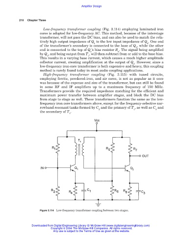
Low-frequency transformer coupling (Fig. 3.114) employing laminated iron
cores is adopted for low-frequency AC. This method, because of the interstage
transformer, will not pass the DC bias, and can also be used to match the rela-
tively high output impedance of Q to the low input impedance of Q . One end
1 2
of the transformer’s secondary is connected to the base of Q , while the other
2
end is connected to the top of Q ’s bias resistor R . The signal being amplified
2 6
by Q , and being output from T , will then subtract from or add to the base bias.
1 1
This results in a varying base current, which causes a much higher amplitude
collector current, creating amplification at the output of Q . However, since a
2
low-frequency iron-core transformer is both expensive and heavy, this coupling
method is rarely found today in most audio coupling applications.
High-frequency transformer coupling (Fig. 3.115) with tuned circuits,
employing ferrite, powdered-iron, and air cores, is not as popular as it once
was because of the expense and size of the transformer, but can still be found
in some RF and IF amplifiers up to a maximum frequency of 150 MHz.
Transformers provide the required impedance matching for the efficient and
maximum power transfer between amplifier stages, and block the DC bias
from stage to stage as well. These transformers function the same as the low-
frequency iron core transformers above, except for the frequency-selective nar-
rowband resonant tanks formed by C and the primary of T , as well as C and
2 1 3
the secondary of T .
1
Figure 3.114 Low-frequency transformer coupling between two stages.
Downloaded from Digital Engineering Library @ McGraw-Hill (www.digitalengineeringlibrary.com)
Copyright © 2004 The McGraw-Hill Companies. All rights reserved.
Any use is subject to the Terms of Use as given at the website.