
Page 288 - Complete Wireless Design
P. 288
Filter Design
Filter Design 287
As with the connecting of multiple half-sections of the low-pass filter, the
high-pass filter will also exhibit a cascading effect. This is due to the increas-
ing selectivity of the cascaded half-sections, and forces the f to increase in fre-
C
quency above what is desired. By using the adjustment factors presented in
Table 6.2, this proclivity can be compensated for.
For example, if the f of a high-pass filter is to be 200 MHz, and a 2-section
C
filter is required, then first multiply the adjustment factor, as found in Table
6.2, of 0.85 times the f of 200 MHz. This equals 170 MHz. Now design the
C
2-section filter as if the f will be 170 MHz, and a high-pass filter with a true
C
f at the desired frequency of 200 MHz will now result.
C
As it was with the low-pass filter design, the high-pass filter attenuation
slope follows the same 18 dB per octave drop for a 3-pole filter, and a 36 dB per
octave drop for a 6-pole filter.
When multiple half-sections are combined with high-pass filter designs, the
filter’s attenuation response becomes that of the amount of the L and C com-
ponents (poles) that result from the combination of these half-sections. For
instance, if a filter is created from three half-sections, which contain six reac-
tive components (poles), it will now contain only four reactive components
(poles) after the appropriate components have been combined. These compo-
nents left after the combination of the half-sections will be the indicator of the
filter’s attenuation response.
An important consideration with all filters, and especially with high-pass
filter designs, is that such a filter is a high-pass filter only up to a certain fre-
quency, after which the stopband becomes disrupted by the eventual self-res-
onance of the filter’s components, as well as the distributed capacitances that
will inevitably let higher frequencies pass through the stopband (Fig. 6.28).
If it is required to block DC from being shunted to ground at the filter’s
input, a high-pass filter must be initiated with a series capacitor, instead of a
shunt inductor.
Bandpass filters. The design of a bandpass filter by image parameters is
quite similar to the low-pass and high-pass filter design procedure just pre-
sented, but the complexity is greater because there are twice the compo-
nents and twice the cutoff frequencies. As with the low-pass and high-pass
filter designs, we also start with a half-section (Fig. 6.29), and can add
either of these half-sections together to obtain a filter with more poles. With
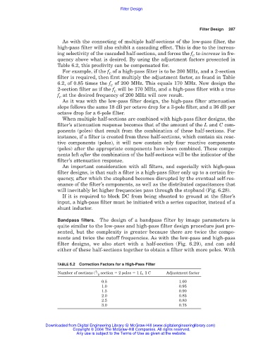
TABLE 6.2 Correction Factors for a High-Pass Filter
1
Number of sections ( section 2 poles 1 L, 1 C Adjustment factor
2
0.5 1.00
1.0 0.95
1.5 0.90
2.0 0.85
2.5 0.80
3.0 0.75
Downloaded from Digital Engineering Library @ McGraw-Hill (www.digitalengineeringlibrary.com)
Copyright © 2004 The McGraw-Hill Companies. All rights reserved.
Any use is subject to the Terms of Use as given at the website.