
Page 291 - Complete Wireless Design
P. 291
Filter Design
290 Chapter Six
and
1
CP
50 (525 MHz 475 MHz)
63.6 pF
2
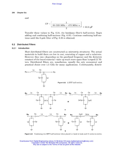
Transfer these values to Fig. 6.34, the bandpass filter’s half-section. Begin
adding and combining half-sections (Fig. 6.35). Continue combining half-sec-
tions until the 6-pole filter of Fig. 6.36 is obtained.
6.2 Distributed Filters
6.2.1 Introduction
Most distributed filters are constructed as microstrip structures. The actual
materials to build them are low in cost, consisting of copper and a substrate.
However, they can—depending on the passband frequency and the dielectric
constant of the board material—take up much more space than lumped LC fil-
ters. Distributed filters are, nonetheless, usually the only economical and
practical choice over 1.5 GHz for many applications. Unfortunately, distrib-
Figure 6.32 A BPF half-section.
Figure 6.33 Combining two BPF half-sections when placed (a) tank-to-tank and (b) series-to-series.
Downloaded from Digital Engineering Library @ McGraw-Hill (www.digitalengineeringlibrary.com)
Copyright © 2004 The McGraw-Hill Companies. All rights reserved.
Any use is subject to the Terms of Use as given at the website.