
Page 292 - Complete Wireless Design
P. 292
Filter Design
Filter Design 291
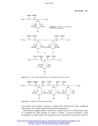
Figure 6.34 Values as calculated
for BPF half-section.
Figure 6.35 (a) Two single half-sections; (b) combining the shunt tanks.
Figure 6.36 Completed 6-pole bandpass filter.
uted filters may display reentrant modes that will destroy their stopband
attenuation at certain repeating harmonic frequencies.
Distributed bandpass filter structures cannot merely be a distributed copy
of a lumped LC filter design. In order to obtain a narrow bandpass, with
acceptable in-band ripple and insertion loss, specialized structures must be
Downloaded from Digital Engineering Library @ McGraw-Hill (www.digitalengineeringlibrary.com)
Copyright © 2004 The McGraw-Hill Companies. All rights reserved.
Any use is subject to the Terms of Use as given at the website.