
Page 289 - Complete Wireless Design
P. 289
Filter Design
288 Chapter Six
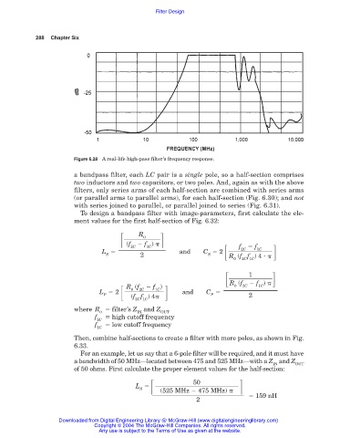
Figure 6.28 A real-life high-pass filter’s frequency response.
a bandpass filter, each LC pair is a single pole, so a half-section comprises
two inductors and two capacitors, or two poles. And, again as with the above
filters, only series arms of each half-section are combined with series arms
(or parallel arms to parallel arms), for each half-section (Fig. 6.30); and not
with series joined to parallel, or parallel joined to series (Fig. 6.31).
To design a bandpass filter with image-parameters, first calculate the ele-
ment values for the first half-section of Fig. 6.32:
R
0
f )
(f
f
f
L and C 2
2C
1C
2C
1C
S 2 S R (f f ) 4
0 2C 1C
1
f )
R (f
1C
f )
0
2C
R (f
2C
1C
0
L 2 and C
P (f f ) 4 P 2
2C 1C
where R filter’s Z and Z
0 IN OUT
f high cutoff frequency
2C
f low cutoff frequency
1C
Then, combine half-sections to create a filter with more poles, as shown in Fig.
6.33.
For an example, let us say that a 6-pole filter will be required, and it must have
a bandwidth of 50 MHz—located between 475 and 525 MHz—with a Z and Z
IN OUT
of 50 ohms. First calculate the proper element values for the half-section:
50
L
S (525 MHz 475 MHz)
159 nH
2
Downloaded from Digital Engineering Library @ McGraw-Hill (www.digitalengineeringlibrary.com)
Copyright © 2004 The McGraw-Hill Companies. All rights reserved.
Any use is subject to the Terms of Use as given at the website.