
Page 297 - Complete Wireless Design
P. 297
Filter Design
296 Chapter Six
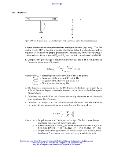
Figure 6.43 (a) A distributed bandstop filter; (b) with equivalent lumped series shunt circuit.
A 3-pole distributed microstrip Butterworth interdigital BP filter (Fig. 6.44). The fol-
lowing 3-pole BPF is fine for a simple distributed filter, but simulation will be
required to optimize for proper performance. Specifically, adjust the spacing S
between elements for improved S and S and to attain your desired bandwidth.
21 11
1. Compute the percentage of bandwidth required at the 3-dB-down points at
the center frequency of interest:
(F F )
u(3dB)
L(3dB)
%BW 100
3db
f
CENTER
where %BW percentage of the bandwidth at the 3 dB points
3dB
F frequency of the upper 3-dB point, Hz
u(3dB)
F frequency of the lower 3-dB point, Hz
L(3dB)
f filter’s center frequency, Hz
CENTER
2. The length of dimension L will be 90 degrees. Calculate the length L, in
mils, of these 90 degree microstrip elements as in “Shorted-Stub Bandpass
Filter,” above.
3. Calculate the width W of the 60-ohm microstrip elements as in “Shorted-
stub bandpass filter,” above.
4. Calculate the length A of the two outer filter elements from the center of
the microstrip input/output transmission lines to the ground via:
F L
A CF L L
F
u
where A length to center of the input and output 50-ohm transmission
line from the center of the ground via.
CF correction factor; if %BW as calculated above is: 30% BW, CF
3dB
1.30; 20% BW, CF 1.35; 10% BW, CF 1.70; 5% BW, CF 2.0
L length of the 90 degree stub, as calculated in step 2 above, from
just below B section to the center of the ground via, in mils
Downloaded from Digital Engineering Library @ McGraw-Hill (www.digitalengineeringlibrary.com)
Copyright © 2004 The McGraw-Hill Companies. All rights reserved.
Any use is subject to the Terms of Use as given at the website.