
Page 301 - Complete Wireless Design
P. 301
Filter Design
300 Chapter Six
There are many different combinations of two-filter diplexers: bandpass-
bandpass, bandpass–low pass, low pass–high pass, etc., depending on the
application.
6.3.2 Diplexer design
A diplexer must be designed as two different-frequency filters with nonover-
lapping passbands. If their passbands are placed too close together, they will
react adversely with each other. This deleterious effect will decrease return
loss and increase insertion loss, while losing passband flatness and symmetry.
In addition, each filter section of a bandpass diplexer should normally begin
with a series resonant pole at the input, and not a shunt element, as a shunt
element can short out the other filter’s frequency of interest and destroy the
return loss of the entire diplexer.
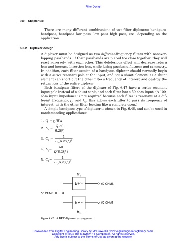
Both bandpass filters of the diplexer of Fig. 6.47 have a series resonant
input pole instead of a shunt tank, and each filter has a 50-ohm input. (A 100-
ohm input impedance is not required because each filter is resonant at a dif-
ferent frequency, f and f ; this allows each filter to pass its frequency of
r1 r2
interest, with the other filter looking like a complete open.)
A simple bandpass type of diplexer is shown in Fig. 6.48, and can be used in
nondemanding applications:
1. Q f /BW
r
Q 50
2. L
2
6.28f
r
1
3. C
2 2
L (6.28 f )
2 r
50
4. L
1
Q(6.28f )
r
1
5. C
1 2
L (6.28 f )
1 r
Figure 6.47 A BPF diplexer arrangement.
Downloaded from Digital Engineering Library @ McGraw-Hill (www.digitalengineeringlibrary.com)
Copyright © 2004 The McGraw-Hill Companies. All rights reserved.
Any use is subject to the Terms of Use as given at the website.