
Page 303 - Complete Wireless Design
P. 303
Filter Design
302 Chapter Six
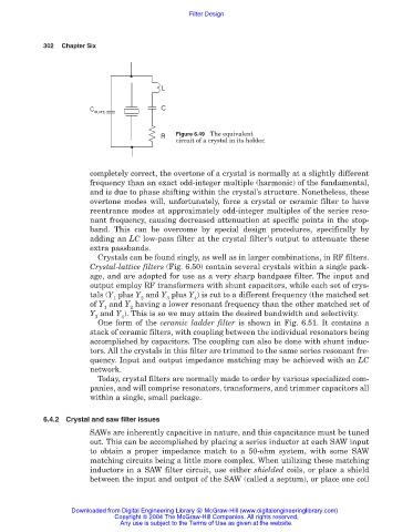
Figure 6.49 The equivalent
circuit of a crystal in its holder.
completely correct, the overtone of a crystal is normally at a slightly different
frequency than an exact odd-integer multiple (harmonic) of the fundamental,
and is due to phase shifting within the crystal’s structure. Nonetheless, these
overtone modes will, unfortunately, force a crystal or ceramic filter to have
reentrance modes at approximately odd-integer multiples of the series reso-
nant frequency, causing decreased attenuation at specific points in the stop-
band. This can be overcome by special design procedures, specifically by
adding an LC low-pass filter at the crystal filter’s output to attenuate these
extra passbands.
Crystals can be found singly, as well as in larger combinations, in RF filters.
Crystal-lattice filters (Fig. 6.50) contain several crystals within a single pack-
age, and are adopted for use as a very sharp bandpass filter. The input and
output employ RF transformers with shunt capacitors, while each set of crys-
tals (Y plus Y and Y plus Y ) is cut to a different frequency (the matched set
1 2 3 4
of Y and Y having a lower resonant frequency than the other matched set of
1 2
Y and Y ). This is so we may attain the desired bandwidth and selectivity.
3 4
One form of the ceramic ladder filter is shown in Fig. 6.51. It contains a
stack of ceramic filters, with coupling between the individual resonators being
accomplished by capacitors. The coupling can also be done with shunt induc-
tors. All the crystals in this filter are trimmed to the same series resonant fre-
quency. Input and output impedance matching may be achieved with an LC
network.
Today, crystal filters are normally made to order by various specialized com-
panies, and will comprise resonators, transformers, and trimmer capacitors all
within a single, small package.
6.4.2 Crystal and saw filter issues
SAWs are inherently capacitive in nature, and this capacitance must be tuned
out. This can be accomplished by placing a series inductor at each SAW input
to obtain a proper impedance match to a 50-ohm system, with some SAW
matching circuits being a little more complex. When utilizing these matching
inductors in a SAW filter circuit, use either shielded coils, or place a shield
between the input and output of the SAW (called a septum), or place one coil
Downloaded from Digital Engineering Library @ McGraw-Hill (www.digitalengineeringlibrary.com)
Copyright © 2004 The McGraw-Hill Companies. All rights reserved.
Any use is subject to the Terms of Use as given at the website.