
Page 305 - Complete Wireless Design
P. 305
Filter Design
304 Chapter Six
6. SAW filters can have odd or even harmonic spurious responses. These spu-
rious responses will degrade the SAW’s stopband attenuation.
7. SAWs can have high time delays through the filter structure of up to 1
s or
more, which are problematic in certain circuits.
SAWs do, however, have a few features that are hard to beat by any other
filter type: They have as close to a brickwall filter response as can be obtained
today, are physically small, do not need to be tuned, and are low cost when
purchased in huge quantities.
6.5 Active Filters
6.5.1 Introduction
Active filters typically use an operational amplifier and an RC filter network
to obtain low-pass, high-pass, and bandpass responses at low frequencies.
Passive RC networks themselves can be employed alone as a simple, non-
resonant filter for certain audio applications, and can be utilized to attenuate
RF, while passing only DC and the low-frequency AC. As an example, the
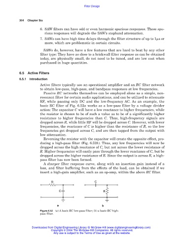
basic RC filter of Fig. 6.52a works as a low-pass filter by a voltage divider
action: The capacitor C will have a low reactance to higher frequencies, while
the resistor is chosen to be of such a value as to be of a significantly higher
resistance to higher frequencies than C. Thus, high-frequency signals are
dropped across R, while little RF will be dropped across C. However, with lower
frequencies, the reactance of C is higher than the resistance of R, so the low
frequencies get dropped across C, and are then tapped from the output with
low attenuation.
Reversing the resistor with the capacitor will create the opposite effect, pro-
ducing a high-pass filter (Fig. 6.52b). Thus, any low frequencies will now be
dropped across the high reactance of C, but not across the lower resistance of
R. Higher frequencies will easily pass through the lower reactance of C, but be
dropped across the higher resistance of R. Since the output is across R, a high-
pass filter has now been formed.
A sharper filter response curve, along with an insertion gain instead of a
loss, and filter buffering from the effects of the load, can be obtained if we
insert a high-gain amplifier, such as an op-amp, within the above RC filter.
Figure 6.52 (a) A basic RC low-pass filter; (b) a basic RC high-
pass filter.
Downloaded from Digital Engineering Library @ McGraw-Hill (www.digitalengineeringlibrary.com)
Copyright © 2004 The McGraw-Hill Companies. All rights reserved.
Any use is subject to the Terms of Use as given at the website.